
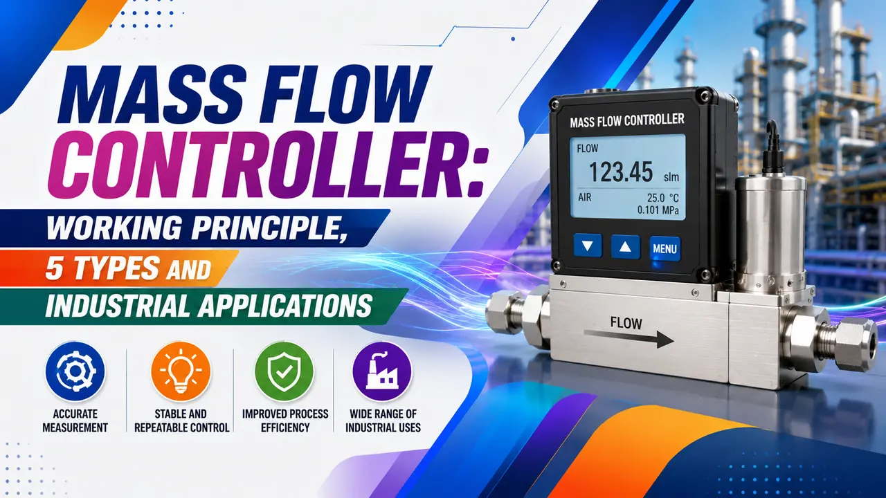
A mass flow controller measures and controls gas or liquid flow by mass, not by volume.
Because mass does not change with temperature or pressure, an MFC delivers a precise, repeatable quantity of fluid regardless of upstream pressure fluctuations -- critical in semiconductor fabrication, pharmaceutical gas mixing, and laboratory research.
This guide covers how an MFC works, gas conversion factors, the four main MFC types, key applications, and an interactive GCF calculator.
An MFC is a flow meter, a PID controller, and a proportional valve in one housing.
The sensor measures actual mass flow, the PID compares it to the setpoint, and the valve adjusts to close the error -- continuously, with response times of 1 to 3 seconds.
How a Mass Flow Controller Works
Every MFC has four core components: a flow sensor, a PID controller, a proportional valve, and the control electronics.
The sensor measures actual mass flow. The PID compares it to the setpoint. The valve opens or closes to bring actual flow to setpoint.
(Thermal / DP / Coriolis)
(compares to setpoint)
(opens / closes)
(at setpoint flow)
Closed loop: the sensor output feeds back to the PID which continuously corrects the valve position to maintain setpoint
The key advantage over a needle valve is automatic correction.
If upstream pressure rises, a needle valve passes more gas. An MFC detects the increase and closes its valve slightly to hold the setpoint -- no operator adjustment needed.
Flow rate is expressed in sccm (standard cubic centimetres per minute) or slm (standard litres per minute), referenced to 0°C and 101.325 kPa.
Standard conditions make the stated flow independent of actual temperature and pressure. See the mass flow vs volumetric flow article for why this matters.
Thermal MFC: The Most Common Type
Most MFCs use the thermal measurement principle. A bypass tube diverts a fraction of gas past two RTDs wound around the tube.
A heater between the RTDs warms the gas. Flowing gas carries heat downstream -- the downstream RTD reads warmer than the upstream RTD. The temperature difference is proportional to mass flow.
ṁ = mass flow rate of gas through the bypass tube (g/s)
Cp = specific heat capacity of the gas at constant pressure (J/g·K)
At zero flow: both sensors read the same temperature (ΔT = 0).
At maximum flow: ΔT is at its calibrated maximum value.
The sensor is calibrated for a specific gas -- Cp differs for every gas.
Gas Conversion Factor (GCF) and Why It Matters
Every thermal MFC is factory calibrated using nitrogen (N2) as the reference gas. If you need to control a different gas, you either use an MFC specifically calibrated for that gas, or you apply a GCF correction to a nitrogen calibrated unit.
MFC reading = what the meter displays (in N2-equivalent sccm)
Actual flow = true volumetric flow of the real gas at standard conditions
If GCF < 1 (e.g. CO2 = 0.74): the meter under-reads -- actual flow is higher than displayed.
If GCF > 1 (e.g. He = 1.454): the meter over-reads -- actual flow is lower than displayed.
N2 GCF = 1.000 (reference, no correction needed).
| Gas | GCF (vs N2) | Effect on Reading | Typical Use |
|---|---|---|---|
| Nitrogen (N2) | 1.000 | Reference -- no correction | Purge gas, carrier gas, general use |
| Argon (Ar) | 1.39 | MFC over-reads -- actual flow is lower | Sputtering, plasma processes |
| Helium (He) | 1.454 | MFC over-reads -- actual flow is lower | Carrier gas, leak detection |
| Oxygen (O2) | 0.993 | Very close to N2 -- small correction | Combustion, oxidation processes |
| CO2 | 0.740 | MFC under-reads -- actual flow is higher | Greenhouse gas research, food processing |
| Methane (CH4) | 0.747 | MFC under-reads -- actual flow is higher | Natural gas research, fuel cells |
| Hydrogen (H2) | 1.010 | Very close to N2 -- very small correction | Semiconductor processing, fuel cells |
| Silane (SiH4) | 0.600 | MFC under-reads significantly | Semiconductor thin film deposition |
Gas Conversion Factor Calculator
5 Types of Mass Flow Controllers
| Type | Measurement Principle | Best For | Limitation |
|---|---|---|---|
| Thermal (bypass) | Temperature difference between two RTDs on a bypass tube -- ΔT proportional to ṁ × Cp | Clean gases, wide range of flows, low cost, most common in semiconductor and lab gas | Gas specific calibration required -- GCF correction needed for different gases |
| Thermal (inline) | Same thermal principle but sensor is in the main flow path -- no bypass tube | Higher flow rates, lower pressure drop than bypass design, corrosive gases | More expensive, sensor exposed to full flow and process chemistry |
| Differential pressure (DP) | Pressure drop across a laminar flow element -- ΔP proportional to flow. See DP transmitter basics. | Corrosive gases, high pressure, where thermal sensing is not compatible | More sensitive to upstream pressure fluctuations than thermal types |
| Coriolis | Coriolis force on vibrating tubes -- true mass flow, fluid independent. See the Coriolis working principle. | Liquids, mixed fluids, applications where fluid properties are unknown or variable | Higher cost, sensitive to vibration, not suitable for very low gas flows |
| Pressure based | Sonic nozzle downstream of a fast proportional valve -- flow calculated from upstream pressure, temperature, and nozzle area | Corrosive and reactive gases, semiconductor processes, high purity requirements | Requires stable upstream supply pressure, minimum 2:1 pressure ratio across nozzle |
Key Industrial Applications
Semiconductor Fabrication (CVD / Etch)
CVD and plasma etch processes require precise gas ratios in the process chamber.
Silane, ammonia, and process gases are each controlled by a dedicated MFC. A ratio error of 1% shifts film composition. Multiple MFCs feed a gas mixing panel on separate channels.
Pharmaceutical and Biotech Gas Blending
Medical gas mixtures (O2 and CO2 for respiratory therapy) require accurate composition control. MFCs deliver each component at a precise flow rate and the mixture flows at their sum.
Accurate blending requires correct GCF settings and regular calibration against certified reference standards.
Industrial Gas Atmosphere Furnaces
Heat treatment furnaces use controlled atmospheres (hydrogen, nitrogen, ammonia) to prevent oxidation or to nitride or carburise parts.
MFCs hold the exact gas ratio regardless of door openings or pressure disturbances. The solenoid valve at the MFC outlet provides a positive shutoff.
Environmental Monitoring and Calibration
Calibration gas generators use MFCs to blend certified span gases for CEMS systems. Flow rate stability directly affects calibration accuracy.
See instrument calibration terminology for traceability requirements.
Laboratory Research and Pilot Plants
Catalyst testing rigs, packed bed reactors, and GC carrier gas systems all use MFCs.
In a packed bed reactor, space velocity is controlled by the MFC setpoint. Changing setpoint adjusts residence time and conversion without touching temperature or pressure.
Fuel Cell and Hydrogen Energy Systems
Proton exchange membrane fuel cells require precise hydrogen and air stoichiometry for efficiency and membrane protection.
MFCs control both anode hydrogen and cathode air flow. The flow calibration and GCF correction are critical -- MFC accuracy directly affects fuel efficiency and stack lifetime.
MFC Selection and Installation Checklist
| Parameter | What to Specify | Why It Matters |
|---|---|---|
| Gas type and purity | Exact gas or mixture composition; purity grade (instrument grade, electronic grade) | Determines wetted material compatibility, required GCF, and whether bypass or inline sensor is needed |
| Flow range | Minimum and maximum operating flow in sccm or slm | Select a full scale range where normal operation falls in the 10 to 90% range for best accuracy |
| Pressure conditions | Inlet pressure (minimum and maximum) and outlet pressure or backpressure | MFCs need a minimum differential pressure across the internal valve (typically 0.3 to 0.5 bar) to control flow |
| Temperature range | Ambient and process temperature range | Affects sensor calibration and elastomer compatibility in the internal valve and seals |
| Wetted materials | Body material (316L SS, Hastelloy), seat and seal material (PCTFE, Kalrez, Viton) | Must be compatible with the process gas -- aggressive gases (fluorine, chlorine, HCl) require special materials |
| Signal interface | 0 to 5V analog, 4 to 20 mA, RS-485, EtherNet/IP, PROFIBUS | Must match the host controller or PLC/DCS input. See the signal conditioning guide. |
| Valve type | Solenoid (on and off capability), piezoelectric (fast response), proportional | Piezoelectric valves give faster response for processes requiring rapid setpoint changes |
Watch: Thermal Mass Flow Controller Working Principle
Mass Flow Controller Questions
External References
- Mass Flow Controller Working Principle and Types -- Bronkhorst
- Mass Flow Control Technology Overview -- MKS Instruments
What We Learn Today
- An MFC is a flow sensor plus a PID controller plus a proportional valve in one housing -- it controls mass flow automatically
- Thermal MFCs measure ΔT across a heated bypass tube: ΔT is proportional to ṁ × Cp of the gas
- GCF correction: Actual flow = MFC reading / GCF -- CO2 GCF = 0.74 means the meter under-reads actual CO2 flow
- Operate an MFC between 10 and 90% of full scale for best accuracy -- below 10% accuracy degrades significantly
- Always install a 2 to 7 micron inlet filter -- particulate contamination of the bypass sensor is the leading cause of drift
- Coriolis and pressure based MFCs are fluid independent -- no GCF correction needed, but cost is higher