
Pressure Measurement · DP Transmitter · Capacitance Cell · Flow · Level · Filter
Differential Pressure Transmitter: Working Principle, Sensing Cell Physics, Five Applications and Interactive Calculator
A DP transmitter measures the difference in pressure between two points and converts it to a 4-20 mA signal. One instrument measures flow, level, density, filter condition and interface, depending only on how you connect it. This guide covers the complete working principle from capacitance cell physics through to the 4-20 mA output, with formulas for all five applications and a live calculator.
What Is a Differential Pressure Transmitter?
A differential pressure (DP) transmitter is an instrument that measures the difference between two pressures applied at its high-pressure (HP) and low-pressure (LP) process connections, and converts that difference into a standardised output signal, typically 4-20 mA, often with superimposed HART digital communication.
The key insight that makes the DP transmitter so powerful is that differential pressure is caused by many different physical phenomena. Fluid flowing through a restriction creates a differential pressure proportional to the square of flow velocity. A column of liquid creates a differential pressure proportional to its height. A blocked filter creates a differential pressure proportional to the degree of blockage. One instrument, three connections, and the right engineering analysis can measure all of these.
DP transmitters are the most widely used measurement instruments in process plants. A typical refinery or chemical plant has hundreds or thousands of DP transmitters measuring flow, level, density, filter differential and interface level simultaneously. The DP transmitter level measurement guide covers the level application in detail; this guide covers the complete instrument from sensing element to output signal.
How a DP Transmitter Works: The Sensing Cell Explained
Inside every modern DP transmitter is a sensing capsule (also called the primary element or sensor cell). The most common type is a capacitance-based sensing cell. Understanding how this cell converts a pressure difference into an electrical signal is the key to understanding the entire transmitter.
Figure 1: DP transmitter internal construction. Process pressure on the HP side deflects the sensing diaphragm through silicone oil fill fluid. The diaphragm moves between two fixed capacitor plates (C1 and C2). As it deflects, C1 increases and C2 decreases. The electronics convert the C1/C2 ratio to a digital pressure value, then output 4-20 mA proportional to the configured span.
The Capacitance Sensing Cell: Physics Explained
The heart of a modern DP transmitter is the capacitance sensing cell. A capacitor stores electrical charge between two parallel plates separated by a dielectric. The capacitance C is given by C = ε × A / d, where ε is the permittivity of the dielectric, A is the plate area and d is the gap between the plates. As d decreases, C increases.
The sensing diaphragm is a thin, flexible metal membrane clamped at its edges between two fixed electrode plates. When HP pressure is higher than LP pressure, the diaphragm deflects toward the LP side. This closes the gap on the HP side (C1 increases) and opens it on the LP side (C2 decreases). The transmitter electronics continuously measure the ratio C1/C2, which is a linear function of the differential pressure applied. This capacitance ratio is then converted by an ADC and microprocessor to a 4-20 mA output.
Piezoresistive Sensing Cells: The Silicon Alternative
Some DP transmitters use a piezoresistive sensing cell instead of capacitance. A silicon diaphragm has strain gauges diffused into it in a Wheatstone bridge configuration. When differential pressure deflects the diaphragm, the silicon strain gauges change resistance due to the piezoresistive effect. The bridge becomes unbalanced by an amount proportional to the applied differential pressure, producing a millivolt output that is amplified and converted to 4-20 mA. Piezoresistive cells typically offer faster dynamic response (useful for surge detection) but slightly more temperature sensitivity than capacitance cells.
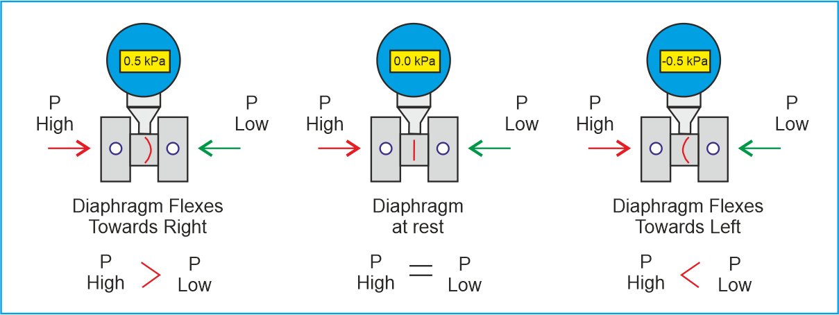
When Pressure at the "H" port greater than the "L" port: Output moves towards 20mA.
When Pressure at the "H" port equal to the "L" port: Output remains at 4mA.
When Pressure at the "H" port less than the "L" port: Output moves towards 4mA.
From Differential Pressure to 4-20 mA: The Output Signal
Where:
I = output current (mA)
DP_measured = differential pressure currently applied (kPa, mbar, inH2O etc.)
LRV = Lower Range Value (DP at 4 mA: the zero of the measurement)
URV = Upper Range Value (DP at 20 mA: the full scale of the measurement)
Example: Transmitter ranged 0-50 kPa DP. Measured DP = 30 kPa. I = 4 + [(30 - 0) / (50 - 0)] x 16
= 4 + [0.60] x 16
= 4 + 9.6
I = 13.6 mA (60% of span)
The LRV does not have to be zero. For a flow application with orifice plate ranged 0-25 kPa DP, LRV=0 and URV=25 kPa. For a level application with zero suppression, LRV may be a positive non-zero value. For zero elevation (wet leg), LRV may be a negative value.
Five Applications of a DP Transmitter: One Instrument, Many Measurements
Flow through a restriction (orifice plate, venturi tube, flow nozzle) creates a differential pressure proportional to the square of the volumetric flow rate. The transmitter outputs the DP; the DCS applies the square root function to get flow. This is the most common DP transmitter application. See our guide on the venturi tube flow meter for the complete Bernoulli derivation.
A liquid column creates a hydrostatic pressure P = ρgh at its base. The HP tap connects at the tank bottom; the LP tap is vented to atmosphere (open tank) or to the vapour space (closed tank). The DP equals the hydrostatic head of the liquid above the HP tap. Our DP level measurement guide covers open tanks, closed tanks, zero suppression and elevation in full.
If the liquid height between HP and LP taps is fixed and known, then DP = ρ × g × h, so ρ = DP / (g × h). A DP transmitter with taps at a fixed vertical distance in a vessel full of liquid measures density directly. Used in sugar mills, chemical reactors and slurry systems where concentration must be monitored continuously without sampling.
A clean filter has a low pressure drop across it. As it accumulates particles, the pressure drop increases. A DP transmitter across an inlet strainer, cartridge filter or bag filter measures this increasing differential pressure continuously. When DP exceeds a setpoint, the DCS raises an alarm for filter change or backwash. This is used in 4-20 mA alarm loops for HVAC filters, process water strainers, and lubrication oil filters.
In a vessel containing two liquids of different densities (oil and water), the DP across a fixed height span depends on how much of each fluid is present. Combined with a total level measurement, the interface position can be calculated. For complex multi-phase vessels, dedicated interface level measurement technologies are used alongside the DP transmitter.
where K = flow coefficient from orifice/venturi design
LEVEL (liquid column): h = DP / (rho x g)
where rho = liquid density (kg/m³), g = 9.81 m/s²
DENSITY: rho = DP / (g x h_fixed)
where h_fixed = fixed vertical distance between taps (m)
FILTER DP: DP_filter = P_upstream - P_downstream
Alarm setpoint = max allowable filter DP from datasheet
INTERFACE LEVEL: h_interface = (DP - rho_upper x g x h_total) / ((rho_lower - rho_upper) x g)
where h_total = total liquid height measured separately
DP Transmitter Calculator: Three Modes
Zero and Span Calibration of a DP Transmitter
Calibrating a DP transmitter sets two points that define the linear relationship between the measured DP and the 4-20 mA output. This must be done correctly before the transmitter enters service, and rechecked at each scheduled calibration interval. Our guide on measurement uncertainty in calibration explains how to document and report calibration results to ISO/IEC 17025.
Purpose: eliminates offset error (output correct at one point)
Typical cause of zero shift: hydrostatic head in impulse lines, temperature effects
SPAN adjustment: sets the output to 20 mA when DP = URV
Purpose: eliminates gain error (output correct at all points)
Typical cause of span shift: fill fluid volume change, diaphragm stiffness change
SMART transmitter (HART): zero and span set via HART communicator Commands: LRV = set LRV to current DP applied (apply 0 DP for zero, apply full DP for span)
Or: Enter LRV and URV values directly as engineering values (kPa, mbar, inH2O)
Calibration tolerance check: Error (%) = [(Output_actual - Output_expected) / Span] x 100
Acceptable limit: typically 0.1% of span for smart transmitters
Always apply zero correction before span correction. Zero error shifts the entire output up or down. Span error changes the slope. If you correct span first and zero second, you must re-check span afterwards.
Critical Installation Pitfalls: The Equalising Valve Sequence
Incorrect operation of the DP transmitter manifold valves is the most common cause of DP transmitter damage and erroneous readings in the field. Every technician working with DP transmitters must know the correct sequence for commissioning and isolation.
| Valve operation | Correct sequence for commissioning | What goes wrong if done incorrectly |
|---|---|---|
| Commissioning (putting into service) | 1. Open equalise valve first (LP = HP, so DP = 0: transmitter sees no differential). 2. Open HP block valve. 3. Open LP block valve. 4. Close equalise valve slowly. Transmitter now sees live DP. | If LP is opened before equalise with HP already open, the full process pressure hits one side of the transmitter with the other at atmosphere. This can permanently over-range and damage the sensing diaphragm if the applied DP exceeds the transmitter's static pressure limit. |
| Taking out of service | 1. Open equalise valve (DP goes to zero). 2. Close HP block valve. 3. Close LP block valve. 4. Close equalise valve. Transmitter is now fully isolated. | If HP is closed first while LP is still open and no equalise, the LP side remains at process pressure while HP side depressurises. The transmitter sees a reversed DP that may exceed the reverse DP limit and damage the capsule. |
| Zero check in field | Open equalise valve with both block valves open. Transmitter should read 4 mA (zero DP). If it reads other than 4 mA, there is a zero offset that needs adjustment via HART communicator. | If block valves are closed and only equalise is opened, the transmitter sees only the pressure trapped in the impulse lines, not process pressure. This zero check is meaningless and may give a false good result. |
Quick FAQs: DP Transmitter Basics
- DP Transmitter Level Measurement: Open Tank, Closed Tank and Wet Leg
- Zero Suppression and Elevation in DP Level Transmitters: Full Calculation Guide
- Venturi Tube Flow Meter: How DP Creates a Flow Signal
- Interface Level Measurement: When DP Transmitters Are Used for Two-Liquid Detection
- 4-20 mA Current Loop: How the DP Transmitter Output Signal Is Wired
- Measurement Uncertainty in Calibration: Documenting DP Transmitter Calibration Results
External References
- Emerson: Differential Pressure Flow Measurement Technology Guide
- Yokogawa: DP Transmitter Selection and Application
- ISO 5167: Measurement of Fluid Flow by Differential Pressure Devices
What we learn today
- A DP transmitter measures the pressure difference between HP and LP connections and outputs 4-20 mA using I = 4 + [(DP - LRV)/(URV - LRV)] x 16. The capacitance sensing cell works by differential pressure deflecting a sensing diaphragm between two capacitor plates: as C1 increases and C2 decreases, the C1/C2 ratio gives a linear pressure reading. Silicone oil fill fluid isolates the sensing capsule from the process.
- One DP transmitter measures five different process variables: flow (Q = K × √DP via orifice/venturi), level (h = DP / ρg via hydrostatic head), density (ρ = DP / g×h_fixed), filter condition (DP = pressure drop across filter element) and interface level (combined with total level measurement). The application is determined entirely by how the HP and LP connections are made.
- Commissioning sequence is critical: always open the equalise valve first, then HP, then LP, then close equalise. Zero always before span in calibration. The LRV is the DP at 4 mA (may be non-zero for suppression or negative for elevation). Zero suppression is needed when the HP tap is below the zero level reference; zero elevation when a wet leg creates a constant back-pressure on the LP side.
1 Comment