
IEC 61131-3 defines five standard PLC programming languages, each suited to a different type of problem.
Knowing when to use each PLC programming language is just as important as knowing how to write code.
This guide compares all five PLC programming languages with syntax examples, real code, application guidance, and a language selector tool.
PLC programming languages are not interchangeable. Ladder Diagram reads like a relay schematic. Structured Text reads like high level code. Sequential Function Chart models a process sequence as a flowchart. Each has a home territory where it outperforms the others.
PLC Programming Languages Defined by IEC 61131-3
Welcome! In this article, we are going to explore all five PLC programming languages defined by the IEC 61131-3 standard. By understanding each PLC programming language, you will be able to choose the right one for every project.
If you have worked with PLCs before, you have probably used Ladder Diagram. But the standard actually gives us four more options, each designed for a different kind of thinking and a different kind of automation problem. By the end of this article, you will know exactly which language to reach for on your next project.
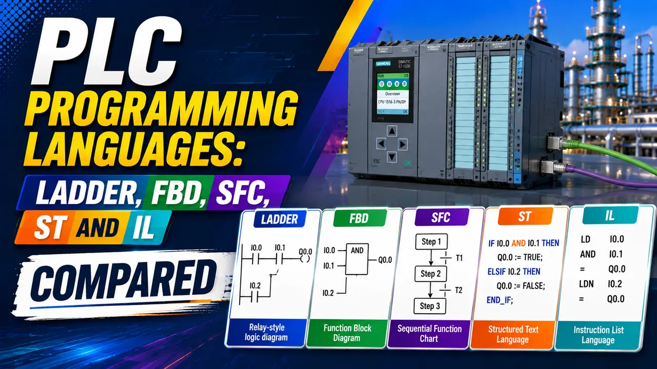
IEC 61131-3 is the international standard that defines PLC programming. It specifies five PLC programming languages so engineers from different backgrounds can work with the same controller.
An electrical engineer reaches for Ladder Diagram because it looks like relay schematics. A software engineer prefers Structured Text because it resembles Pascal or C.
A process engineer uses Sequential Function Chart because it mirrors a process flow diagram. Click any term to expand.
All 5 PLC Programming Languages Explained in Detail
1. Ladder Diagram (LD)
Ladder Diagram represents the program as horizontal rungs between two vertical power rails.
Contacts on the left represent input conditions. A coil on the right represents the output action. If all contacts on a rung are true, the coil energises.
It maps directly to relay panel logic, which is why electricians adopt it quickly. Every PLC manufacturer supports it.
It is the default choice for simple machine logic, motor starters, and conveyor control. See the Ladder Logic for Beginners guide for a full introduction.
Use when: the team has an electrical background, the logic is mostly discrete on/off, and the program must be maintained by field electricians who are not software engineers.
Avoid when: the program needs complex arithmetic, loops, or data array processing. These require many rungs of Ladder that are hard to read and harder to debug.
2. Function Block Diagram (FBD)
Function Block Diagram represents the program as a network of interconnected blocks. Each block is a function: a PID controller, a timer, a comparator, a filter. Data flows from left to right through the connections between blocks.
FBD maps naturally to instrument loop thinking. A PID block has a setpoint input, a process variable input, and an output signal -- connect them the same way you would draw a loop diagram.
The DCS function block programming guide covers FBD in DCS systems where it is the dominant choice.
Use when: the program is primarily continuous control (PID, cascade, ratio control), the team comes from an instrumentation background, or the program is running in a DCS style environment.
Avoid when: the program has complex sequential logic. FBD is excellent for continuous loops but becomes a tangled mess of connections when used for step-by-step sequences.
3. Sequential Function Chart (SFC)
Sequential Function Chart models a process as a series of rectangular steps joined by horizontal transition bars. The program sits in exactly one active step at a time. When the transition condition below the active step becomes true, the program moves to the next step.
SFC is the clearest way to represent a batch sequence or machine cycle. A filling machine: Step 1 open inlet valve, Step 2 wait for level, Step 3 close valve, Step 4 open discharge.
Each step has an action list and each transition has a condition expression. The sequence is visible without reading code. See the sequential circuits article.
Use when: the program is a sequence of distinct steps with clear entry and exit conditions: batch reactors, filling machines, CIP/SIP cycles, robot programs.
Avoid when: the control is purely continuous (use FBD) or purely parallel discrete logic (use LD). SFC is a sequencer, not a general purpose language.
4. Structured Text (ST)
Structured Text is a high level text language with IF THEN ELSE, CASE, FOR, WHILE, and REPEAT constructs. Variables, data types, and function calls work similarly to Pascal or modern C. It is the most expressive of the five PLC programming languages for algorithmic work.
Use when: the program needs mathematical formulas, array manipulation, string processing, or algorithm implementation. Also excellent for reusable function blocks where readability matters more than graphical representation.
Avoid when: the maintenance team is electricians with no programming background. ST code is not readable to someone who learned PLCs through relay logic. Combine ST with LD by writing complex calculations in ST function blocks called from a Ladder main program.
5. Instruction List (IL)
Instruction List is a low level assembly like language. Each line is one instruction operating on an accumulator register. It was included in the original IEC 61131-3 standard as a bridge for engineers coming from relay instruction sets and early PLC programming.
Important: the 2013 edition of IEC 61131-3 deprecated Instruction List. Most modern PLC platforms are removing IL support. For new projects, Structured Text performs the same role with far better readability. Do not start new programs in IL. Use another PLC programming language instead.
PLC Programming Language Selector
PLC Programming Languages Comparison Table
| Language | Type | Best Application | Strengths | Limitations |
|---|---|---|---|---|
| Ladder (LD) | Graphical | Discrete machine logic, motor control | Familiar to electricians, easy to trace, universal support | Poor for complex maths, loops, or sequential process |
| Function Block (FBD) | Graphical | PID loops, signal processing, continuous control | Maps to instrument loop diagrams, reusable blocks | Messy for sequential logic, many connections hard to read |
| Sequential FC (SFC) | Graphical | Batch processes, machine cycles, recipes | Process sequence visible at a glance, models state clearly | Not general purpose, requires other languages for step actions |
| Structured Text (ST) | Text | Complex calculations, data arrays, algorithms | Compact, expressive, similar to high level languages | Not readable by electricians, no graphical representation |
| Instruction List (IL) | Text | Legacy systems only | Compact, close to hardware | Deprecated in IEC 61131-3 2013. Use ST for new work. |
Mixing Languages in One Project
IEC 61131-3 allows all five PLC programming languages in the same project. This is a deliberate design choice.
A typical process plant project uses several PLC programming languages together, one per program unit. The main program runs in SFC. Each step calls a Ladder Diagram subroutine for discrete I/O logic.
Continuous control loops run as FBD function blocks. Complex alarm calculations use Structured Text.
This approach lets each section use the PLC programming language that suits it best. The key rule is consistency within each module. Do not mix PLC programming languages inside the same rung or function block.
Application Matching Guide
Conveyor and Motor Control
Ladder Diagram. The start stop seal logic, safety interlocks, and running feedback all map directly to relay logic rungs. Every electrician on site can read and modify it. See the PLC counter instructions for counting conveyor cycles in LD.
PID Temperature Control
Function Block Diagram. Connect the temperature transmitter input to the PID block PV input, the setpoint from HMI, and the output to the heater control. The loop structure is visible on screen. See the PLC timer instructions for delay logic used in heater cycling.
Batch Reactor Sequence
Sequential Function Chart. Each phase of the batch (charge, heat, react, cool, discharge) becomes a step. Transition conditions are process values reaching target. The recipe is readable by both engineers and operators. See the sequential circuits article for the underlying state machine logic.
Flow Calculation and Totalling
Structured Text. Square root extraction, flow equation with correction factor, daily totaliser with reset -- these fit in 10 lines of ST but would need 40 or more rungs of LD.
Compile into a reusable function block called from the main program. See the shift register article for data queue patterns.
Watch: PLC Programming Languages Explained
PLC Programming Languages Questions
External References
What We Learn Today
- IEC 61131-3 defines 5 PLC programming languages: LD, FBD, SFC, ST, and IL
- Ladder Diagram suits discrete machine logic and teams with electrical backgrounds
- Function Block Diagram suits continuous PID control and instrumentation engineers
- Sequential Function Chart suits batch processes and machine cycles with distinct steps
- Structured Text suits complex calculations, loops, and data processing tasks
- Instruction List is deprecated -- use Structured Text for all new text based PLC programs