
A loop check verifies every component in the instrument loop is correctly installed, wired, powered, and configured before the process is started.
For a pressure transmitter, this covers the physical signal path from the process connection to the DCS input card, including HART configuration, mA accuracy, and alarm setpoints.
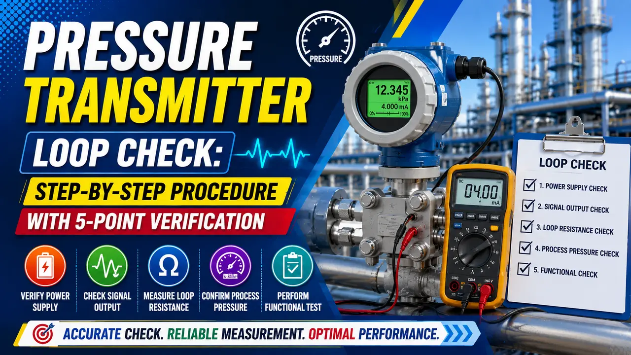
This guide covers the complete cold loop and hot loop check procedure, the 5-point mA verification table, HART checks, and a live loop check calculator.
A loop check does not adjust anything. It verifies the already configured transmitter delivers the correct signal to the control system. Any adjustment is a separate calibration activity done before the loop check.
Pressure Transmitter Loop Check: What Must Be Ready Before Starting
A loop check can only be completed when all components of the loop are installed and available. Starting before the loop is ready wastes time and generates a false record. Confirm each of the following before issuing the loop check permit.
| Item | Requirement | Document to Check |
|---|---|---|
| Transmitter installed | Mounted, process connection made, impulse lines installed and leak tested | Hook up drawing, P&ID |
| Wiring complete | Field cable pulled and terminated at both the transmitter junction box and the marshalling cabinet or I/O card | Loop diagram, cable schedule |
| Power available | 24 VDC loop supply energised and correct polarity confirmed at transmitter terminals | Electrical drawing, loop diagram |
| DCS or PLC configured | Tag name, engineering units, LRV, URV, alarm setpoints, and failsafe mode all configured in the control system | Instrument datasheet, I/O list |
| Transmitter calibrated | Zero and span already set to match the instrument datasheet range -- loop check verifies, not calibrates | Calibration certificate |
| HART parameters verified | Tag, LRV, URV, damping, and output units set correctly in the transmitter via HART communicator or configurator | Instrument datasheet, vendor configuration sheet |
| Safety clearance | Isolation, lockout and permit to work confirmed for the instrument loop area -- especially if process lines may be under pressure | PTW system, site safety rules |
Cold Loop Check: Step by Step Procedure
A cold loop check is done with the process isolated and no actual pressure on the transmitter.
The signal is simulated using a HART communicator or loop calibrator to confirm wiring, control system scaling, and HART settings before process fluid is admitted.
Confirm Power and Signal at Transmitter Terminals
Measure DC voltage across the transmitter supply terminals. Should read 12 to 30 VDC.
If below 12V, the transmitter cannot operate correctly -- check loop supply voltage and total resistance. Minimum terminal voltage at 20 mA is 12V for most smart transmitters. See the loop impedance guide.
Check HART Configuration with Communicator
Connect a HART communicator across the transmitter terminals (or across the 250 ohm HART resistor). Verify: tag number, LRV, URV, output units (bar, kPa, psi), and damping setting -- all must match the instrument datasheet.
Also confirm output mode is set to 4 to 20 mA linear (not square root, unless this is a DP flow transmitter). See the HART protocol guide.
Simulate 4 mA Output and Check at DCS
Use the HART communicator to force the transmitter output to 4.000 mA. The DCS engineering display should show the LRV (e.g. 0 bar). Record the DCS reading.
A discrepancy means the DCS tag scaling does not match the transmitter LRV -- correct the DCS configuration before proceeding.
Simulate 20 mA Output and Check at DCS
Force the output to 20.000 mA. The DCS display should show the URV (e.g. 10 bar). Record the reading.
If LRV is correct but URV is wrong, the DCS tag has a span error -- check URV in the DCS I/O configuration. The zero shift article explains the difference between a DCS scaling error and a transmitter error.
Verify Alarm and Trip Setpoints
Simulate the output at each alarm setpoint in turn (LAL, HAL, LALL, LAHH). Confirm each activates at the correct DCS value with the correct alarm text and priority.
Record any discrepancy. Do not sign the loop check sheet until all alarms pass.
Verify Failsafe Direction
Disconnect one wire momentarily to simulate a broken loop. The DCS should go to the configured failsafe -- upscale (21 mA equivalent) or downscale (3.6 mA equivalent) depending on the process safety requirement.
Confirm the direction matches the datasheet. Reconnect the wire and confirm the reading returns to the simulated value.
Release Forced Output and Confirm Transmitter Returns to Normal
Release the HART forced output. With the process isolated, the transmitter measures atmospheric pressure (gauge types).
The DCS should show a value close to the LRV. If the reading is far from expected at atmosphere, the transmitter zero is incorrectly set -- resolve this calibration issue before the hot loop check.
5-Point Verification Table
During the hot loop check, actual reference pressure is applied at five points. Record both the actual mA at the transmitter output and the DCS engineering unit reading at each point.
| Formula | mA = 4 + ((P -- LRV) / (URV -- LRV)) x 16 | |
|---|---|---|
| Example range: 0 to 10 bar (LRV = 0, URV = 10) | Tolerance: ±0.1 mA (±0.625% of span) -- tighten if accuracy class demands it | |
Loop Check Calculator
Hot Loop Check: With Live Process Pressure
The hot loop check applies actual process pressure to the transmitter and verifies the reading at the DCS against an independent reference (a calibrated pressure gauge or deadweight tester). This is the final acceptance test before handover to operations.
Slowly Admit Process Pressure
Open the root valve slowly to admit process pressure. Watch for leaks at the impulse lines, manifold, and transmitter connections -- isolate immediately if any are found.
The transmitter output should move from its at atmosphere value toward the live process pressure reading.
Confirm Process Value at DCS Matches Reference
Compare the DCS reading with a calibrated reference gauge at the same process tap. The difference should be within the transmitter accuracy specification (typically ±0.1 to ±0.5% of span).
A larger difference indicates calibration error, impulse line problem, or wrong range. See the DP transmitter guide.
Apply 5-Point Check Using the Process Pressure
Where the process allows, apply all 5 check points using actual pressure and record DCS reading against the reference gauge at each point.
Where pressure cannot be held at specific values, compare DCS to reference gauge at all observed points throughout the available range.
Verify Transmitter Damping Response
Create a step change by briefly opening a bypass valve. The DCS reading should respond within the configured damping time (typically 0 to 2 seconds).
A sluggish response indicates damping is too high or the impulse line is partially blocked. See the damping and response time guide.
Sign Off and Record in the Loop Check Sheet
Both the field technician and the commissioning engineer must sign the loop check sheet.
Record the tag number, date, each test point result, and any corrective actions taken. The signed sheet becomes the instrument history record.
Common Loop Check Failures and Causes
| Failure Observed | Most Likely Cause | Corrective Action |
|---|---|---|
| DCS reads correct at 4 mA but wrong at 20 mA (span error) | URV in DCS does not match transmitter URV; or transmitter span is incorrect | Verify and match URV in DCS tag configuration and transmitter HART configuration. Recalibrate span if transmitter output is off. |
| DCS reads wrong value at both 4 and 20 mA (offset error) | LRV mismatch between DCS and transmitter; or constant wiring resistance adding a voltage offset | Check DCS LRV setting against transmitter LRV. Measure actual loop current at transmitter terminals vs DCS mA input reading -- a difference indicates wiring or card fault. |
| DCS reads bad quality or 0 at all times | Open circuit in field cable, blown fuse, or power supply fault | Measure voltage at transmitter terminals. If below 12V or 0V, trace the power supply fault. Measure continuity of each wire. |
| Alarm does not trigger at correct value | Alarm setpoint in DCS configured in wrong units (e.g. bar vs psi), or set to wrong value | Check DCS alarm configuration units and setpoint against instrument datasheet alarm setpoint in the same units. |
| Reading drifts slowly after settling | Transmitter damping too high; or impulse line partially blocked | Check damping setting via HART -- reduce to minimum and re-test. Check impulse line vents and root valve position. |
| Failsafe goes wrong direction on wire break | Failsafe configured as upscale when process requires downscale (or vice versa) | Change failsafe direction in HART configuration to match the process safety requirement on the datasheet. |
| HART communicator cannot connect | No 250 ohm resistor in loop; loop resistance too low for HART superimposed signal | Insert a 250 ohm HART resistor in series in the loop. See the HART protocol guide. |
Watch: Loop Test and Checking of Pressure Transmitter
Pressure Transmitter Loop Check Questions
External References
- Loop Checking Procedure -- DIVIZE Industrial Automation
- Pressure Transmitter Installation and Calibration Field Guide -- Microcybers
What We Learn Today
- A loop check verifies wiring, DCS scaling, and alarms -- it does not adjust anything; calibration comes first
- Cold loop check uses simulated mA (HART forced output); hot loop check uses actual process pressure with a reference gauge
- Expected mA at any point: mA = 4 + ((P -- LRV) / span) x 16
- 5-point check (0, 25, 50, 75, 100%) plus reverse order detects offset, span error, non linearity, and hysteresis
- Minimum transmitter terminal voltage at 20 mA = 12V; use the calculator to verify loop compliance before energising
- Both the field technician and commissioning engineer must sign the loop check sheet before handover to operations