
A control valve is only as accurate as the positioner that drives it, and a small zero or span error can leave a valve passing when the DCS thinks it is shut. A careful calibration routine makes every milliamp give the travel the loop expects.
Positioners drift as linkages wear, springs relax and feedback parts loosen. A structured positioner calibration with a five point stroke test restores the link between the 4 to 20 mA signal and real valve travel.
What Is Positioner Calibration?
Positioner calibration is the procedure that matches the input signal, usually 4 to 20 mA, to the actual travel of the control valve, so that 4 mA gives the closed position, 20 mA gives full open and every point between follows a straight line. How the positioner compares signal and feedback is explained in control valve positioner working, so this article focuses on the calibration itself.
The job covers zero and span setting, a stroke test at fixed points, checks of fail action and, for smart devices, a review of tuning and alerts. The signal side follows the basics of the 4 to 20 mA current loop.
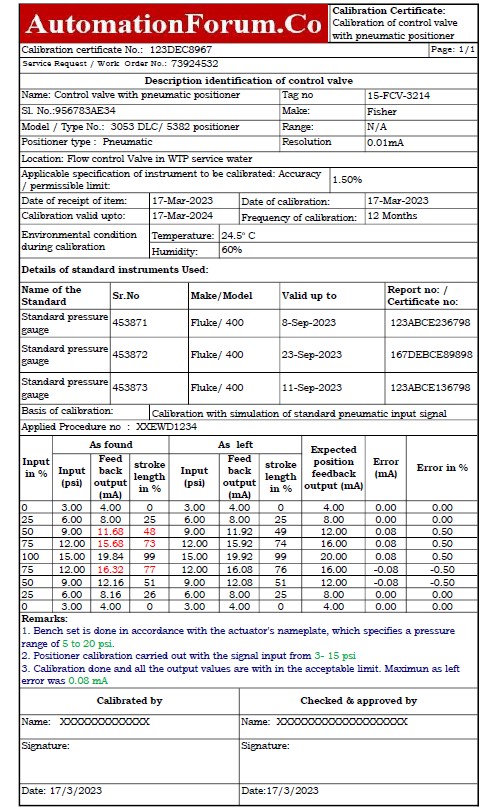
The sample report above shows the usual format, with input signal, expected travel, measured travel and error at each test point. Keeping both as found and as left readings is what turns a routine job into traceable maintenance.
When Positioner Calibration Is Needed
Fluke points out that a valve may be stroked from hundreds to tens of thousands of times in one year. That constant motion wears feedback linkages, cams and pins, and every bit of play shows up as a zero or span error.
Plan a positioner calibration after installation, after any actuator or linkage work, after replacing the positioner and at the interval set by your plant, as discussed in calibration interval determination.
A digital positioner does not just record two end points during auto calibration. Emerson states that the DVC6200 also seeks its minor loop feedback and output bias, which tune the internal pressure control.
Tools and Preparation for Positioner Calibration
- Work permit and agreement from operations to stroke the valve
- Loop in manual or valve bypassed and isolated
- Clean, dry instrument air at the nameplate supply pressure
- Calibrated mA source or multifunction calibrator
- HART communicator or asset software with the correct device description
- Dial gauge or travel scale fixed to the yoke
- Datasheet showing fail action, travel and signal range
- Blank calibration sheet for as found and as left readings
Air quality matters because moisture and oil block the tiny nozzles and spool valves inside the positioner, as explained in dew point risks in instrument air. A multifunction process calibrator can source mA and read pressure at the same time.
Record the as found readings before positioner calibration begins. Without them you cannot judge drift, set a sensible interval or prove that the valve was in tolerance before the work.
8 Proven Positioner Calibration Steps
The as found and as left terms are explained in instrument calibration common terms. During a smart positioner calibration, steps 4 to 6 are done through the local menu or a HART tool, while older pneumatic units use zero and span screws.
Auto Positioner Calibration Versus Manual Zero and Span
In auto calibration the positioner drives the valve to both mechanical stops, stores the end points and then runs a short tuning routine. The Emerson DVC6200 manual notes that if auto calibration does not finish within its time limit, the selected tuning set may not suit the valve response.
Manual positioner calibration is used when auto calibration fails or when the valve must stop short of a hard stop. The same manual describes analog adjust, used when the mA source can be changed by hand, and digital adjust, used when it cannot, with the valve set to 0, 100, 5 and 95 percent travel in turn.
A 3 to 15 psi signal moves a beam and flapper nozzle, with zero and span screws.
An I/P stage plus a mechanical beam, set with zero and span adjusters.
A microprocessor with travel sensor, auto calibration and diagnostics.
Digital setpoint over Foundation Fieldbus or PROFIBUS PA.
Fluke suggests that the start of valve opening can be set between 4.1 and 4.2 mA so that there is no counter pressure at 4 mA. Many digital positioners do the same job with a tight shutoff or cutoff setting that drives the actuator fully to the seat below a chosen signal.
Five Point Stroke Test and Error Formula
The stroke test applies 0, 25, 50, 75 and 100 percent signal, first rising and then falling, and compares measured travel with expected travel. Approaching each point from one direction only hides hysteresis, so always record both directions.
Measured travel % = Measured stroke ÷ Rated stroke × 100
Error % of span = Measured % minus Expected %
I in mA; I low and I high are the signal range of this valve
Example:
Range 4 to 20 mA, input 12 mA, rated stroke 50 mm, measured 24.6 mm
Expected = (12 minus 4) ÷ 16 × 100 = 50.00 percent
Measured = 24.6 ÷ 50 × 100 = 49.20 percent
Error = minus 0.80 percent of span, within a 1 percent tolerance
Positioner calibration tolerance comes from the plant procedure or the loop requirement, and 1 percent of span is a common choice for control valves. Accuracy and error terms are covered in instrument accuracy and error.
Positioner Calibration Error Calculator
Second Worked Example: Split Range Valve
In split range control, one controller output drives two valves, for example valve A over 4 to 12 mA and valve B over 12 to 20 mA. For valve B, enter 12 and 20 mA as the signal range in the calculator above.
At 16 mA, valve B should be at (16 minus 12) ÷ 8 × 100 = 50 percent travel. If its 40 mm stroke reads 21.0 mm, measured travel is 52.5 percent and the error is plus 2.5 percent, which fails a 1 percent tolerance and needs a span correction.
On split range valves, write the signal range on the calibration sheet header. Technicians who assume 4 to 20 mA by habit are the most common cause of split range errors after a turnaround.
Checking Fail Action and Direct or Reverse Settings
Fail action must match the datasheet and the process safety need, as explained in fail safe valve positions. During positioner calibration, cut the air supply and then the signal separately, and confirm that the valve moves to its safe position each time.
The positioner action decides whether rising signal raises or lowers output pressure, and it must suit both the actuator type and the control requirement. A reverse acting actuator with a wrongly set direct positioner will move the valve the wrong way, which the five point test reveals at once.
I/P Converter and Analog Positioner Checks
On analog electro pneumatic positioners, the I/P stage converts 4 to 20 mA into a pneumatic signal, often 3 to 15 psi. Check its output with a test gauge at 4, 12 and 20 mA before adjusting the positioner, since a faulty I/P will make any mechanical adjustment pointless.
In many analog positioners, zero and span adjustments interact with each other. Changing the span shifts the zero slightly, so technicians repeat zero then span two or three times until both settle.
Using HART Tools for Smart Positioners
A HART communicator connects across the loop and lets you run auto calibration, adjust travel cutoffs, change tuning and read alerts, all using the HART protocol. The loop needs at least 250 ohms of resistance for HART communication to work, as explained in the HART loop resistor article.
Before positioner calibration, read and save the existing configuration so you can restore it if needed. The Emerson DVC6200 manual lists a default travel deviation alert at 5 percent for 9.99 seconds, a setting worth reviewing for critical valves.
Troubleshooting Positioner Calibration Problems
| Symptom | Likely Cause | Remedy |
|---|---|---|
| Auto calibration fails or times out | Wrong tuning set, low supply, loose linkage | Check air and linkage, choose a suitable tuning set |
| Valve does not reach 100 percent | Low supply pressure, travel stop, wrong span | Raise supply to nameplate, check stops, recalibrate span |
| Valve hunts at a fixed signal | High friction, excessive gain, leaking tubing | Check packing and tubing, lower tuning gain |
| Large up and down difference | Linkage play or sticky packing | Tighten linkage, inspect packing |
If the valve passes positioner calibration on the bench but behaves badly in the loop, check the signal path with the instrument loop checking procedure. Wider valve problems are covered in control valve troubleshooting.
Fluke advises a slow ramp check after positioner calibration, and the valve should not oscillate or hunt at any step. If it does, look at tuning and friction before blaming the positioner.
- Accurate valve position for every controller output
- Tight shutoff and full capacity when needed
- Early detection of linkage and air problems
- Traceable records for audits
- Valve must be taken off line or bypassed
- Auto routines trust mechanical stops as given
- Cannot correct high friction or trim wear
- Needs skilled staff and correct tools
Where Careful Calibration Matters Most
For emergency shutdown valves, the stroke check links naturally with partial stroke testing of ESD valves.
Fisher DVC6200 Instruction Manual
Auto Calibration Demonstration Video
Positioner Calibration FAQ
It is the procedure that matches the input signal to actual valve travel, so 4 mA closes and 20 mA fully opens the valve. Every point between should follow a straight line within tolerance.
The job includes zero and span setting, a five point stroke test and checks of fail action. Smart devices also need a review of tuning and alert settings.
Most procedures use 0, 25, 50, 75 and 100 percent of the signal range. For a 4 to 20 mA valve these are 4, 8, 12, 16 and 20 milliamps.
Readings are taken while the signal is rising and again while it is falling. The difference between the two directions shows hysteresis and dead band in the valve.
The positioner drives the valve to both ends of its travel and stores those positions as zero and full open. Many digital units then run a short tuning routine.
Emerson states that the DVC6200 also finds its minor loop feedback and output bias. Afterwards a manual stroke test still confirms the result against real travel.
Each valve is calibrated over its own part of the signal, for example valve A from 4 to 12 milliamps and valve B from 12 to 20 milliamps. The span of each positioner is then set to that smaller range.
The expected travel formula uses the valve range instead of the full 4 to 20 milliamp signal. Always confirm the ranges from the control narrative before starting the positioner calibration.
Many plants accept 1 percent of span for normal control valves at each test point. Critical loops may use a tighter limit set by the process engineer.
The tolerance should be written in the positioner calibration procedure before any work begins. That way every technician on the team judges pass or fail in exactly the same way.
Hunting usually comes from high friction, very high tuning gain or a leak in the actuator tubing. Positioner calibration only sets the end points and does not cure any of these causes.
Check the packing load and tubing joints first, then reduce gain if needed. A valve signature or step test helps confirm the real reason.
You need a calibrated milliamp source, a HART communicator or asset software and a reliable way to measure stem travel. A test gauge for checking supply pressure is also very useful.
The communicator must carry the correct device description for the exact positioner model. Save the existing configuration before you change any setting during positioner calibration.
Related Articles
- Control Valve Positioner Working
- Split Range Control Working Principle
- Fail Safe Valve Positions
- HART Protocol: How It Works
- Multifunction Process Calibrator Uses
External References
- Fisher FIELDVUE DVC6200 Instruction Manual, Emerson
- How to Keep Control Valve Positioners on Target, Fluke
- Highway Addressable Remote Transducer Protocol, Wikipedia
What We Learn Today
- Positioner calibration matches the 4 to 20 mA signal to real valve travel through zero and span setting, auto calibration and a careful five point stroke test.
- Expected travel equals the signal above the low limit divided by the range, so split range valves use their own range such as 12 to 20 mA.
- Record as found and as left readings in both directions, check fail action and keep the HART configuration saved before changing any setting.
