Pressure Transmitter Installation Best Practices for Gas, Liquid and Steam

Share:
Pressure Measurement
Pressure Transmitter Installation Best Practices for Gas, Liquid and Steam

The location and orientation of a pressure transmitter relative to the process tap is the single biggest factor affecting measurement accuracy in the field.

A correctly specified transmitter can still produce errors of 0.5 to 2% if the impulse lines are routed incorrectly or the tap position is wrong.

Gas Service Liquid Service Steam Service Impulse Line Condensate Pot

Installation best practices for pressure transmitters differ depending on whether the fluid is a gas, liquid, or steam.

Each service requires a different transmitter position, impulse line slope, and ancillary equipment to get a reliable reading.

Hello everyone, today we are going to learn about pressure transmitter installation best practices for gas, liquid and steam service.

We will cover the correct transmitter position and impulse line orientation for each fluid type, the role of condensate pots in steam service, common installation mistakes, and a comparison of the key rules across all three services.
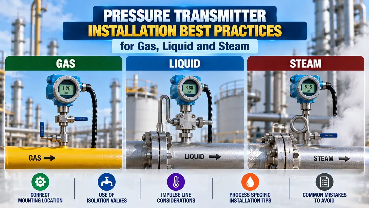
pressure transmitter installation

Pressure Transmitter Installation Best Practices: The Three Service Types

Gas Service

Mount transmitter above the tap. Impulse line slopes downward toward the tap. Condensate drains back to the process, not into the transmitter.

Liquid Service

Mount transmitter below the tap. Impulse line slopes upward toward the tap. Air bubbles rise back to the process, keeping the line full of liquid.

Steam Service

Mount transmitter below the tap. Use a condensate pot to buffer steam from the sensor. Impulse line slopes downward toward the pot, then to the transmitter.

Advertisement

Gas Service Installation Rules

For gas pressure measurement, the transmitter must be installed above the process tap. The tap itself should be on the top or upper side of the pipe.

Any condensate that enters the line drains back toward the tap and away from the transmitter. If mounted below the tap, condensate would collect and create a false liquid head error.

Tap position
Top or upper side of the pipe. This prevents liquid slugs from entering the impulse line when the gas carries moisture or condensable vapour.
Transmitter position
Above the process tap. Condensate flows downward by gravity, back toward the process and away from the transmitter sensing element.
Impulse line slope
Slope downward at minimum 1:10 from the transmitter toward the process tap. No low points in the line where liquid can pool. A trapped liquid pocket introduces a constant pressure offset error.
Drain trap
Install a condensate trap at the lowest point of the impulse line if the gas carries significant moisture. The trap captures liquid before it reaches the transmitter connection. Drain periodically.
Common gas service mistake: Routing the impulse line with a low point (a U-shape or sag) between the tap and the transmitter. Condensate collects in the low point and creates a standing liquid column that adds a constant pressure offset to every reading. The offset changes over time as the liquid evaporates or the trap fills. The error is silent and difficult to detect without a loop check.

Liquid Service Installation Rules

For liquid pressure measurement, the transmitter must be installed below the process tap. The tap should be on the side of the pipe, not the top or bottom.

The impulse line slopes upward from the transmitter to the tap, keeping it full of liquid. Any gas bubble that enters rises back to the process.

Tap position
Side of the pipe. A top tap can allow gas to enter the impulse line. A bottom tap risks sediment or solids entering the impulse line and blocking it.
Transmitter position
Below the process tap. The liquid column in the impulse line stays full and stable. Gas pockets cannot accumulate because they rise back to the process.
Impulse line slope
Slope upward at minimum 1:10 from the transmitter toward the tap. No high points in the line. A high point traps a gas bubble that compresses and expands with pressure changes, introducing dynamic errors.
Hot liquids
For high-temperature liquids, allow enough impulse line length to cool the fluid before it reaches the transmitter. Do not install the transmitter directly at the tap where process temperature exceeds the transmitter's rated temperature limit.
The temperature effect on pressure transmitter accuracy is a common source of error in liquid service. A transmitter mounted close to a hot pipe or vessel will experience ambient temperature swings that shift the zero. Keep the transmitter away from direct process heat and radiant heat sources such as steam tracing.
Advertisement

Steam Service Installation Rules

Steam service has the most demanding installation requirements. Steam must never contact the transmitter sensing element directly.

A condensate pot is installed between the steam tap and the transmitter. It fills with condensate and forms a liquid buffer, keeping steam away from the diaphragm.

Tap position
Upper half of the pipe. This prevents liquid condensate from flowing back from the tap into the pipe and creating impact when steam rushes past the opening.
Condensate pot
Mount the condensate pot above the transmitter and as close to the tap as practical. The pot fills with condensate and creates a stable liquid column. The transmitter sees water pressure, not steam temperature. The pot must be the same height on both sides for a differential pressure installation.
Transmitter position
Below the condensate pot. The liquid column from the pot to the transmitter is a constant known head. This constant offset can be zeroed out during transmitter calibration or suppressed electronically.
Impulse line slope
Slope downward from the tap to the condensate pot, so condensate drains into the pot and fills it. Slope downward again from the pot to the transmitter, so the liquid head is stable and consistent.
Heat tracing
Do not heat trace the impulse lines in steam service. The lines need to be cooler than the steam tap so that condensate forms and fills the pot. Heat tracing prevents condensate from forming and leaves steam in contact with the transmitter.
Common steam service mistake: Forgetting to fill the condensate pot before commissioning. If the pot is empty when the transmitter is first put into service, hot steam enters the impulse line and can damage the transmitter diaphragm. Always fill both pots with clean water before opening the process isolation valve for the first time.

Comparison: Gas vs Liquid vs Steam Installation Rules

RuleGas ServiceLiquid ServiceSteam Service
Tap positionTop or upper side of pipeSide of pipeUpper half of pipe
Transmitter positionAbove the tapBelow the tapBelow the condensate pot
Impulse line slopeDownward toward tap (1:10 min)Upward toward tap (1:10 min)Downward to pot, then to transmitter
Main risk to avoidCondensate pooling in low pointsGas bubble trapped in high pointsSteam reaching the transmitter directly
Special equipmentDrain trap if moisture is highNone for standard serviceCondensate pot required
Temperature concernUsually not an issueCool transmitter away from hot liquidNever heat trace impulse lines
Commissioning stepDrain any test water before startupVent air from impulse line at startupPre-fill condensate pot with water

Other Common Installation Mistakes to Avoid

Manifold valve
Always use a 3-valve manifold for gauge or absolute transmitters, and a 5-valve manifold for differential pressure transmitters. Never open and close isolation valves without following the correct sequence to avoid over-ranging the sensing element.
Vibration
Do not mount the transmitter directly on a vibrating pipe or pump. Vibration causes fatigue failure of the diaphragm and spurious signal noise. Mount the transmitter on a separate instrument stand or bracket isolated from the vibration source.
Impulse line length
Keep impulse lines as short as practical. Long impulse lines increase the response time of the measurement and introduce more potential for leaks and temperature gradients. A maximum of 15 metres is a practical guideline for most applications.
Freeze protection
For outdoor installations in cold climates, heat trace and insulate the impulse lines and the transmitter enclosure. A frozen impulse line blocks pressure transmission entirely and may rupture the tubing. Use glycol or steam tracing and verify the tracing is working before winter each year.
Electrical wiring
Use shielded cable for the 4 to 20 mA signal wiring. Ground the shield at one end only (typically the control room end). Keep signal cables away from power cables and variable frequency drives to prevent interference on the output signal.

Watch: Pressure Transmitter Installation for Gas, Liquid and Steam

Advertisement

Pressure Transmitter Installation Questions Engineers Ask

Where should a pressure transmitter be installed for gas service?
Above the process tap, with the tap on the top or upper side of the pipe. The impulse line slopes downward toward the tap so condensate drains away from the transmitter.
Where should a pressure transmitter be installed for liquid service?
Below the process tap, with the tap on the side of the pipe. The impulse line slopes upward toward the tap, keeping it full of liquid. Gas bubbles rise back to the process.
Why is a condensate pot required for steam pressure measurement?
The condensate pot fills with condensed water and forms a liquid buffer between the steam tap and the transmitter. This keeps hot steam from contacting the sensing diaphragm, which would damage it and cause zero drift.
What is the minimum slope for a pressure transmitter impulse line?
A minimum slope of 1:10 is the general guideline. This allows liquid to drain in gas service and gas to rise in liquid service. Some standards specify 1:12 as the minimum.
What happens if a gas service transmitter is installed below the tap?
Condensate collects at the transmitter and creates a false pressure offset that changes over time as the condensate level changes. The error is difficult to detect without isolating and draining the line.

Related Articles on This Site

External References

Advertisement

What We Learn Today

  • Gas service: transmitter above the tap, impulse line sloping down. Liquid service: transmitter below the tap, impulse line sloping up. Steam service: condensate pot required, transmitter below the pot.
  • Impulse lines must slope at minimum 1:10. No high points in liquid service (traps gas). No low points in gas service (traps liquid). Steam service: slope toward the condensate pot.
  • In steam service, pre-fill the condensate pot before opening the process valve. Never heat trace steam impulse lines. Always mount on a vibration-free stand and use shielded signal cable.
I hope you like above blog. There is no cost associated in sharing the article in your social media. Thanks for reading!! Happy Learning!!

Leave a Reply

Your email address will not be published. Required fields are marked *