
A pressure transmitter calibrated perfectly in a comfortable workshop can still read wrong once it's bolted onto a hot pipe outdoors in summer.
Nothing inside the instrument broke. Temperature simply did what temperature always does to sensitive electronics and mechanical parts.
Pressure transmitter temperature effect is the change in a transmitter's accuracy caused by ambient or process temperature moving away from the reference temperature it was calibrated at, and it shows up as two separate errors: zero shift, where the reading drifts even at zero pressure, and span shift, where the output scale itself stretches or compresses.
Pressure Transmitter Temperature Effect: The Basics
Pressure transmitter temperature effect is one of those specifications students often skim past on a datasheet, right up until a field reading doesn't match what the process actually looks like. Once that happens, it stops being a footnote and starts being the first thing an instrument technician checks.
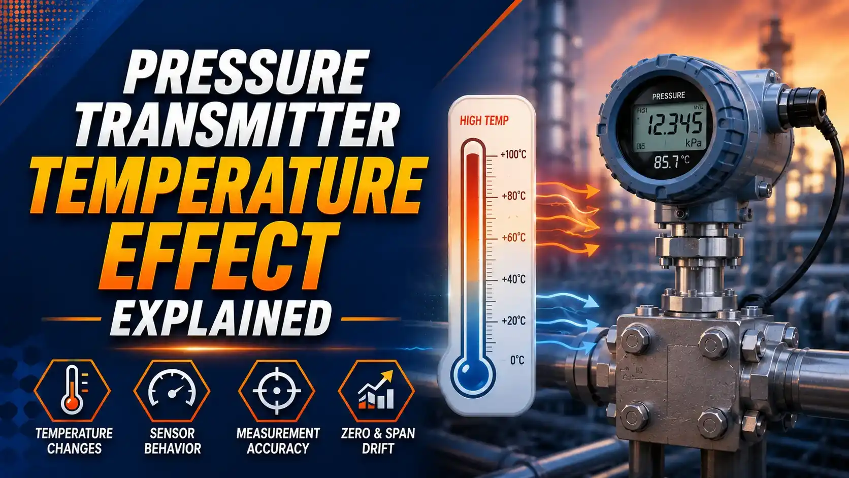
Here's the simple version. Every pressure transmitter is calibrated at one reference temperature, usually somewhere around 20°C or 68°F. The moment the transmitter operates at a different temperature, whether that's a freezing outdoor tank farm in January or a steam line running well above 100°C, its accuracy specification changes too. Manufacturers publish exactly how much it changes, and that published number is what we call the temperature effect.
Why does this matter for someone learning instrumentation? Because "accuracy" on a datasheet is never one fixed number. It's a starting point that gets worse as ambient conditions drift away from ideal, and temperature is usually the single biggest contributor to that drift.
Two Kinds of Error: Zero Shift and Span Shift
Think of zero shift as the instrument lying to you a little, even with no pressure applied at all. A transmitter sitting at zero pressure should output exactly 4 mA (on a standard 4-20 mA loop), but temperature can nudge that baseline up or down.
Span shift works differently. It doesn't affect the zero point much, but it changes how the output scales as pressure increases, so the error grows larger the closer you get to full scale. Most real transmitters experience a mix of both effects at once, and datasheets typically lump them together into one combined temperature effect number.
Why Heat and Cold Actually Change the Reading
It helps to picture what's physically happening inside the transmitter. Most modern units use a sensing element, often a silicon strain gauge or a capacitive diaphragm, that converts pressure into an electrical signal.
That sensing element is made of real materials, and real materials expand, contract, and change their electrical properties with temperature. A silicon strain gauge's resistance shifts slightly with heat. A capacitive sensor's dielectric properties respond to temperature too. Even the amplifier and signal-conditioning electronics downstream of the sensor drift a little as their operating temperature changes.
None of this means the transmitter is faulty. It's simply physics working exactly as expected, and manufacturers design compensation circuits specifically to cancel out most, but never quite all, of this drift.
Try It: Temperature Effect Error Calculator
Most datasheets express temperature effect as a percentage of the Upper Range Limit (URL) per 100°F (or per 55°C) of temperature change. Use this calculator to see how much extra error that adds to a transmitter's base accuracy.
Let's Walk Through a Real Number
Say a technician installs a transmitter with a 1500 psi URL, but the actual process only needs a 150 psi calibrated span. That's a 10:1 turndown ratio, which is common but not always wise, as we're about to see.
The base accuracy is 0.075% of span, which works out to a tiny 0.1125 psi at 150 psi span. Comfortable so far. But the ambient temperature swings 50°F above the reference point, and the datasheet lists a temperature coefficient of ±0.25% of URL per 100°F.
The math gives us: 0.25% × (50 ÷ 100) = 0.125% of URL, and 0.125% of 1500 psi = 1.875 psi. Suddenly that tiny 0.1125 psi base error is joined by a much larger 1.875 psi temperature error, for a total of about 1.99 psi, or 1.32% of the 150 psi span.
Notice what happened there. The temperature effect, because it's specified against URL rather than span, completely dominates the total error once turndown gets aggressive. That's a lesson worth remembering the next time someone chooses a wide-range transmitter for a narrow-range job.
Turndown Ratio Makes Temperature Effect Worse
All three bars assume the same 50°F temperature swing and the same 0.25%URL/100°F coefficient. The only thing changing is turndown ratio, and the effect on span-relative error is dramatic. A student learning instrument sizing should take one thing away from this chart: matching the transmitter's range closely to the actual process range isn't just good practice, it directly limits how badly temperature can hurt accuracy.
How Manufacturers Fight Back Against Temperature Drift
Digital Temperature Compensation
A built-in temperature sensor measures the transmitter's internal temperature, and onboard electronics apply a correction curve, learned during factory calibration, to cancel out most of the drift in real time.
Matched Material Selection
Engineers pair sensing elements and structural materials with similar thermal expansion coefficients, reducing mechanical stress that would otherwise translate into a false pressure reading as temperature changes.
Thermal Isolation and Remote Seals
For genuinely hot or cold processes, capillary remote seals physically separate the sensing diaphragm from the electronics housing, keeping the temperature-sensitive circuitry closer to ambient conditions.
Typical Temperature Effect by Transmitter Class
Per Beamex's breakdown of pressure transmitter accuracy specifications, these ranges aren't fixed rules, but they're a fair rule of thumb when comparing transmitters on paper before checking the actual datasheet numbers.
Good Habits for Managing Temperature Effect
✓ Do
- Match transmitter range to the actual process range instead of defaulting to a wide, general-purpose URL
- Read the temperature effect specification as %URL per 100°F, and convert it to %span before comparing transmitters
- Consider remote seals or thermal isolation when process temperature runs far from ambient
- Recalibrate transmitters after they've been relocated to a location with a very different ambient temperature
✗ Don't
- Compare two transmitters' accuracy specs without checking whether temperature effect is included
- Assume a high turndown ratio is "safe" just because base accuracy looks small on paper
- Ignore ambient temperature swings at outdoor or unconditioned installation sites
- Confuse process fluid temperature with the transmitter's own housing and electronics temperature
A Couple of Good Reads if You Want to Go Deeper
Questions Students and Technicians Often Ask
External References
- Pressure Transmitter Accuracy Specifications: The Small Print, Beamex
- Temperature Specifications for Pressure Transducers, Core Sensors
What we learn today
- Pressure transmitter temperature effect adds extra error whenever operating temperature moves away from the calibration reference point.
- It appears as two separate behaviors, zero shift (the baseline drifts) and span shift (the output scale itself stretches or compresses).
- A worked example shows a 10:1 turndown transmitter picking up nearly 2 psi of temperature-driven error from a 50°F swing, far more than its base accuracy alone.
- Because temperature effect is specified against URL, not span, matching transmitter range closely to the process range is one of the simplest ways to limit its impact.
- Digital compensation, matched materials, and remote seals are the main tools manufacturers use to keep temperature effect small.