
A DCS doesn't run on lines of code the way a PC application does.
It runs on small, reusable pieces called function blocks, wired together like an electrical circuit made of software.
DCS function block programming builds control strategies from small, standardized blocks like AI, AO, and PID, wired together to move a signal from field transmitter to final control element.
Ask a control systems engineer to explain how a DCS actually controls a process, and function blocks are where the answer starts. Every reading, calculation, and output in the system passes through one.
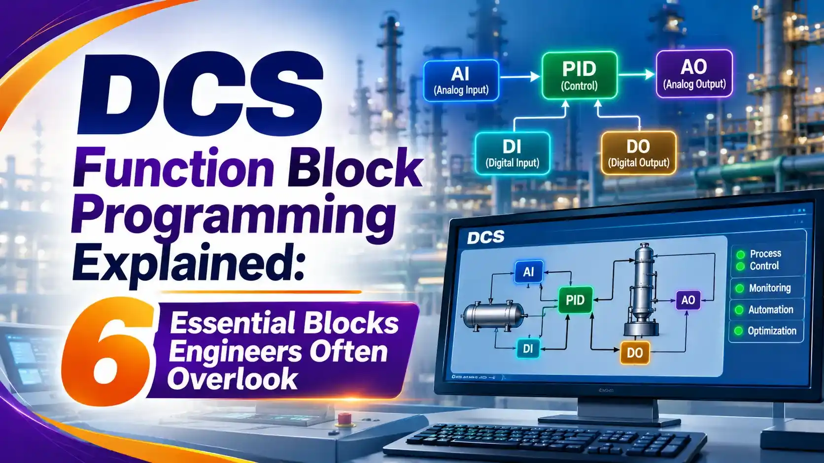
This is fundamentally different from a general purpose program written line by line. A function block is a self contained algorithm with defined inputs, outputs, and parameters, and engineers wire these blocks together visually rather than typing procedural code.
That graphical approach is formally defined under IEC 61131-3, the international standard covering programmable controller languages. Function Block Diagram, or FBD, is one of five languages the standard recognizes, alongside Ladder Logic, Structured Text, Instruction List, and Sequential Function Chart.
The 6 Essential DCS Function Blocks
Nearly every control strategy in a DCS is built from combinations of these six block types.
AI (Analog Input)
Reads a single measurement, such as 4 to 20 mA or a HART digital value, and converts it to engineering units.
AO (Analog Output)
Drives a final control element, converting a calculated value into a 4 to 20 mA signal to a valve or drive.
DI (Discrete Input)
Reads a single on/off status, like a switch, limit sensor, or interlock permissive.
DO (Discrete Output)
Drives a single on/off device, such as a motor starter, solenoid, or alarm horn.
PID (Proportional-Integral-Derivative)
Compares a process variable to a setpoint and calculates the corrective output every scan cycle.
Calculation and Logic Blocks
Perform math, comparisons, timers, and Boolean logic, often feeding safety interlocks and permissives.
Anatomy of a Function Block
Every function block, regardless of type, shares the same basic structure inside the engineering database.
Understanding these four pieces makes any vendor's configuration screen easier to read, whether it's DeltaV, CENTUM VP, or an Allen-Bradley PLC running FBD.
Two blocks of the exact same type can behave completely differently once their parameters and tag names are set. The definition gives the algorithm, but the tag name and parameters give it a job.
How a Signal Flows Through a Simple Control Loop
The classic example is a single PID loop controlling flow through a control valve.
Reads flow transmitter, scales to engineering units
Compares flow to setpoint, calculates output
Converts output to 4-20 mA, drives the valve
The AO block also sends a signal back to the PID block, called back calculation. If the final control valve can't fully reach the commanded position, this feedback prevents the PID's integral term from winding up uselessly.
Cascade Control: Two PID Blocks Working Together
Not every loop is this simple. Cascade control links a primary PID block's output directly into a secondary PID block's setpoint.
A classic example pairs a slow level loop with a fast flow loop feeding it. The level controller's output becomes the flow controller's setpoint, letting the fast inner loop reject disturbances the outer loop alone would miss.
This structure is described in detail in ControlGuru's cascade control architecture guide, and a worked DCS example appears in this step by step cascade loop diagram walkthrough.
IEC 61131-3 Programming Languages Compared
FBD is only one of five standardized languages a DCS or PLC engineer might use.
Function Block Diagram (FBD)
Graphical blocks wired together, the dominant language for continuous process control in a function block diagram system.
Sequential Function Chart (SFC)
Steps and transitions describing a sequence, standard for batch process control and startup procedures.
The AI Block: Where Real World Data Enters the System
The AI block is where a DCS meets the physical process. It has to do more than pass a number through.
It scales the raw signal, checks for out of range faults, and applies alarm limits before anything downstream ever sees the value.
Modern digital communication protocols let an AI block pull far more than just the process variable from a smart transmitter, including diagnostics and secondary variables.
The PID Block: The Workhorse of Process Control
Nothing in a DCS library gets used more than the PID block. It runs the proportional, integral, and derivative math that keeps a process variable at setpoint.
Modern PID blocks do far more than the textbook equation suggests. Emerson's own DeltaV PID function block white paper documents features like dynamic reset limiting and cascade aware tuning that go well beyond a simple formula.
Every PID block also carries a mode attribute, typically Manual, Auto, or Cascade. In Manual, the operator directly sets the output.
In Auto, the block calculates output from its own setpoint and process variable. In Cascade, its setpoint comes from another block upstream instead of an operator entry.
Switching cleanly between these modes without a sudden jump in output is called bumpless transfer, and it's one of the details that separates a well engineered DCS function block programming strategy from a rough one that upsets the process every time an operator changes modes.
Kp = proportional gain, Ki = integral gain, Kd = derivative gain
A real DCS PID block also adds bias, output limits, and back calculation
for bumpless transfer between Manual, Auto, and Cascade modes.
Logic and Interlock Blocks
Not every block modulates a valve. Logic blocks like AND, OR, and comparators build the permissives and interlocks that keep equipment safe.
These sit right alongside process control blocks in the same function block diagram, though safety critical logic is more often handled by a dedicated safety system, as covered in this site's SIS safety lifecycle guide.
Function Block Types Compared
Here's a quick reference for where each block type typically lives and what it actually does.
| Block Type | Typical Location | Primary Function |
|---|---|---|
| AI | Controller I/O card or field transmitter | Reads and scales a process measurement |
| AO | Controller I/O card or valve positioner | Drives a final control element |
| DI / DO | Controller I/O card | Reads or drives an on/off signal |
| PID | Controller (occasionally in field devices) | Calculates a corrective control output |
| Logic/Calc | Controller | Math, comparisons, interlocks, sequencing |
Where Function Block Programming Is Used
Refineries
Distillation column temperature and pressure control loops.
Power Generation
Boiler drum level and combustion control strategies.
Water Treatment
Chemical dosing and clarifier level control loops.
Pharmaceutical Batch
Sequential recipe steps built from SFC and FBD together.
Oil and Gas Processing
Separator level and pressure cascade control.
Pulp and Paper
Consistency and flow control across the production line.
Troubleshooting a DCS Function Block Strategy
When a loop misbehaves, the fastest diagnosis usually starts right inside the function block itself, not the physical wiring.
Most DCS engineering tools let a technician step through a strategy online, watching live input and output values on every block in the chain.
A PID stuck in Manual mode, an AI reading a frozen value, or an AO clamped at a limit are all visible immediately this way, long before anyone needs to check a terminal strip in the field.
Getting comfortable reading these live values is one of the fastest ways to build real proficiency in DCS function block programming, since the block diagram itself becomes the troubleshooting map.
Module Scheduling and Execution Order
A DCS controller doesn't run all its function blocks at once. It scans through them in a defined order, over and over, many times per second.
Execution index controls that order within a module. If a calculation block reads a value from an AI block, the AI block has to execute first in the same scan, or the calculation reads stale data from the previous cycle.
Larger strategies get organized into control modules, treated as a single named entity even though they may contain a dozen or more linked blocks internally. This modularity is what makes strategies portable between similar equipment and easy to troubleshoot one piece at a time.
Execution speed also varies by block type. A fast AI block feeding a PID loop might scan every 250 milliseconds, while a slow calculation feeding an operator display might only need to update once every few seconds, and DCS engineers assign different execution rates accordingly to balance controller load.
Foundation Fieldbus: When Function Blocks Live in the Field
Not every function block has to run inside the DCS controller. Foundation Fieldbus pushes that same block concept out into smart field instruments themselves.
In a fieldbus loop, the AI block naturally lives in the transmitter, since only the transmitter can measure the process. The AO block lives in the valve positioner, since only the valve can act on the process.
The PID block, interestingly, can live in either device. This flexibility is explained in detail in this Foundation Fieldbus function block logic guide, which walks through exactly how AI, PID, and AO blocks link together without a separate controller in the loop at all.
This distributed intelligence is part of where the "distributed" in DCS actually comes from historically, even though most modern systems still centralize the bulk of their control execution in redundant controllers rather than the field devices themselves.
Redundancy in Function Block Execution
Critical loops can't afford to lose control just because one input card fails. Many DCS platforms support dual redundant I/O specifically for this reason.
A special selector block reads from two physically separate input modules simultaneously, and automatically switches to the healthy one if a fault develops on either channel. Yokogawa's CENTUM VP documentation describes this exact mechanism for its dual redundant analog input configuration.
The PID block downstream never needs to know a failover happened. It keeps reading a single, continuous process variable regardless of which physical card is actually supplying the data underneath it.
Do's and Don'ts of Function Block Configuration
✓ Do
- Use clear, consistent tag naming across every module
- Wire back calculation signals to prevent integral windup
- Document execution order for interdependent blocks
- Reuse vendor tested library blocks instead of custom logic
✗ Don't
- Leave alarm limits at default values without process review
- Mix safety interlocks into basic process control modules
- Ignore execution index when blocks depend on each other's output
- Skip bumpless transfer testing between Manual and Auto modes
Live PID Output Preview Calculator
Enter a setpoint, process variable, and proportional gain to see the proportional term's contribution to controller output.
Reference Materials on DCS Function Block Programming
FAQs on DCS Function Block Programming
External References
- Function Block Diagram, Wikipedia
- Digital PID Controllers, Control.com Textbook
- The Cascade Control Architecture, ControlGuru
- Key Features of the DeltaV PID Function Block, Emerson
- Common Process Loop Algorithms Using the PIDE Instruction, Rockwell Automation
What we learn today
- DCS function block programming builds control strategies from standardized blocks like AI, AO, DI, DO, PID, and logic blocks, wired together instead of coded line by line.
- Every block shares the same anatomy: a definition name, a unique tag name, configurable parameters, and an execution index.
- A simple loop flows AI to PID to AO, with a back calculation signal returning from AO to PID to prevent integral windup.
- Cascade control links a primary PID block's output into a secondary PID block's setpoint, letting a fast inner loop handle disturbances.
- FBD is one of five IEC 61131-3 languages, and while the concept is standardized, block libraries differ from vendor to vendor.