
Every field signal in a plant must land on the right channel of the right card, and one missing row can delay a whole loop check. A clean, well structured signal register is the map that system engineers, panel builders and commissioning teams all follow.
The IO list records every signal between the field and the control system, with its tag, type, range and channel. Built carefully, it sizes the hardware, guides the panel builder and drives loop checks right through commissioning.

What Is an I/O List?
An IO list is the project document that lists every input and output signal exchanged between field devices and the control system, one row per signal, with its tag, signal type, range and assigned channel. It covers analog and digital signals of the kinds explained in signals in instrumentation: AI, AO, DI and DO.
The list starts from the piping and instrumentation diagram and the instrument index, then grows as motor, valve and package signals are added. System engineers use it to size cards and cabinets, and the panel builder uses it to wire terminals.
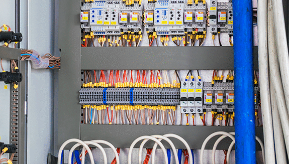
The image shows why the list matters at panel level, since every row becomes a terminal, a channel and some space in a cabinet. Spare capacity planned in the list decides how easily the plant can grow later.
How the I/O List Fits With Other Instrument Documents
The instrument index lists every instrument once, while the I/O list lists every signal, so a single control valve with a positioner and two limit switches gives one index row but three signal rows. The cable schedule then shows how each signal travels from the device to the junction box and on to the cabinet.
Because the control system tag database is often generated straight from the spreadsheet, a typing error in a range or tag travels into the controller. Keeping one master copy under revision control prevents most of these errors.
A single smart control valve can need four signals: the 4 to 20 mA output, two limit switch inputs and sometimes a position feedback input. Counting valves instead of signals is a classic cause of undersized I/O hardware.
10 Essential I/O List Columns
| No | Column | What It Holds |
|---|---|---|
| 1 | Tag number | Unique tag such as FT 1101 or XV 2203 |
| 2 | Service description | Plain words, for example Reactor feed flow |
| 3 | P&ID reference | Drawing number and revision |
| 4 | Signal type | AI, AO, DI, DO, RTD, TC, pulse or fieldbus |
| 5 | Range and units | Calibrated range, for example 0 to 25 m³/h |
| 6 | Power and wiring | Loop powered 2 wire, 4 wire, dry contact, 24 V DC |
| 7 | Hazardous area and IS | Zone, gas group and whether intrinsically safe |
| 8 | Fail state and action | Fail open, fail closed, NO or NC contact |
| 9 | System allocation | Controller, rack, slot and channel |
| 10 | Cable and junction box | Cable number, JB, marshalling terminal |
Many projects add columns for alarm set points, HART enable, sequence of events flag, SIS or BPCS system and remarks. Keep the first ten fixed and in the same order on every project, so that everyone can read any I/O list at a glance.
The power column follows the transmitter style described in 2 wire and 4 wire transmitters. It decides whether the card supplies loop power or the field device has its own supply.
Write the service description in plain words that operators use, not only in codes. It becomes the faceplate text on the DCS and saves confusion in the control room.
Signal Types and Typical Cards
4 to 20 mA from transmitters, often with HART, plus RTD and thermocouple inputs.
4 to 20 mA to positioners, VFD speed references and I/P converters.
24 V DC or dry contact status from switches and MCC feedback.
24 V DC or relay output to solenoids, starters and lamps.
Each type needs a matching card, as described in DCS I/O card types explained. Output cards differ too, and relay, transistor and triac options are compared in PLC output module types.
Intrinsic Safety and Segregation Rules
Signals from hazardous areas must be marked IS or non IS in the I/O list, because they need barriers or isolators and separate wiring. The two protection methods are compared in explosion proof vs intrinsically safe instruments.
Allocate redundant transmitters, such as a 2 out of 3 trip group, to different cards so one card failure cannot take out the whole function. Keep safety signals in the SIS and plant control in the BPCS, following the safety instrumented function design rules.
Spare Philosophy in Practice
Control Design reports a common rule of thumb of 10 to 20 percent spare I/O and terminals. It also describes a 10, 10, 10 approach, meaning 10 percent installed spare per I/O type, 10 percent for expansion and 10 percent spare space.
The same article notes a WAGO recommendation of 5 percent spare for large I/O count projects and 10 percent for smaller ones. AutomationDirect guidance quoted there suggests 20 to 25 percent spare installed terminal blocks, with 10 percent as a minimum.
Sydney Water, in its instrumentation and control specification, requires each cubicle to have at least 20 percent spare space and at least 25 percent spare terminals. It also asks that field devices drive 20 mA through a 600 ohm load at 24 V DC.
I/O List Formula for Channel and Card Count
Cards = Ceiling (Channels with spare ÷ Channels per card)
Example: AI 120, AO 40, DI 200, DO 80, spare 20 percent, 16 channel cards
AI = 120 × 1.2 = 144, cards = 144 ÷ 16 = 9
AO = 40 × 1.2 = 48, cards = 3
DI = 200 × 1.2 = 240, cards = 15
DO = 80 × 1.2 = 96, cards = 6
Total = 528 channels on 33 cards
Real projects also split counts by IS and non IS, by redundancy and by cabinet, then round each group up separately. Remote cabinets near the process, discussed in remote I/O and distributed I/O, follow the same rule.
I/O Count Calculator
Second Worked Example: A Small Pump Skid
Take a skid with 2 pumps, 6 transmitters, 2 control valves and 4 on off valves with two limit switches each. The signals are 6 AI, 2 AO, 4 DO for the on off solenoids, 8 DI for limit switches and 6 DI for pump run, trip and remote status, giving 14 DI in total.
Add 2 DO for pump start and stop commands, giving 6 DO, then apply 20 percent spare to get 8 AI, 3 AO, 17 DI and 8 DO. With 8 channel cards that needs 1, 1, 3 and 1 cards, which a quick check of the I/O list confirms before ordering hardware.
Steps to Prepare an I/O List
Vendor package panels often arrive with their own signal lists, which must be merged and checked for duplicate tags. Field to cabinet wiring practice is explained in PLC wiring from field instrument to system cabinet.
- Every P&ID instrument signal appears in the I/O list
- Each row has a unique tag and clear description
- Ranges and units match the instrument datasheets
- IS signals are on IS cards with barriers or isolators
- Redundant signals are on different cards
- Spare channels exist for every signal type
- Cable and junction box numbers match the cable schedule
- Revision cloud and date shown for every change
Freeze the I/O list before the system vendor starts the database and FAT. Changes after that point should go through a formal change request with a cost and schedule check.
Using the List During FAT and Commissioning
During the factory acceptance test, each channel is simulated and the result is ticked against the I/O list. On site, the same sheet becomes the record for cold loop and hot loop testing.
The marshalling cabinet terminal numbers in the list let technicians trace any signal quickly during faults. Adding a sequence of events flag also helps the team configure the sequence of events recording in DCS.
Many system vendors can import the spreadsheet directly to build the controller database automatically. A clean column structure therefore saves days of manual typing and removes a whole class of tag errors.
- Accurate sizing of cards, cabinets and power supplies
- Clear scope for vendors and panel builders
- Faster FAT, loop check and commissioning
- Easy planning of future expansion
- Needs constant updating as the design changes
- Errors propagate into the database and drawings
- Several versions in circulation cause confusion
- Vendor package signals are often missed
Where the I/O List Is Used
For HART enabled channels, mark the HART flag so that asset management can reach each transmitter, as explained in how HART works. A complete I/O list stays useful for the whole life of the plant, not just during the project.
Instrumentation and Control Specification PDF
Creating an Input Output List Video
I/O List FAQ
It is a project document that lists every input and output signal between field devices and the control system. Each row holds one signal with its tag, type, range and channel.
Engineers use it to size the hardware and to build the control database. Panel builders and commissioning teams use it to wire and test every loop.
The instrument index has one row for each instrument, along with its type, datasheet and location. The I/O list has one row for each signal that reaches the control system.
A single valve with a positioner and two limit switches is one index row. The same valve becomes three signal rows, which is why counts from the index alone fall short.
The core columns are tag, service, P&ID reference, signal type, range, power, hazardous area status and fail state. Allocation to controller, rack, slot and channel completes the core set.
Add cable and junction box references to tie it to the cable schedule. Extra columns such as alarm limits or HART flags can follow as the project needs.
Control Design describes 10 to 20 percent spare I/O as a common rule of thumb. Some specifications ask for more, such as 25 percent spare terminals in each cabinet.
Apply the spare to every signal type and hazardous area class separately. A large overall spare still fails if one type has no free channel left.
Intrinsically safe signals need barriers or isolators and their own segregated wiring. Mixing them with normal signals on one card breaks the protection concept completely.
Marking IS status in the I/O list lets engineers count IS channels correctly for each cabinet. It also tells the panel builder which terminals need blue marking and physical separation.
The instrument and control engineering team usually prepares it from the P&ID, the motor list and the instrument index. The system vendor then adds the final channel allocation and checks it carefully.
One person should own the master I/O list and control every revision. Clear ownership prevents the classic problem of several conflicting versions circulating on site.
Count each signal type, add the agreed spare percentage and round up to whole channels. Then divide by the channels per card and round up again for the card count.
Do this separately for IS and non IS signals and for each cabinet. The calculator above performs the basic version of this count for you.
Related Articles
- Signals in Instrumentation: AI, AO, DI, DO
- DCS I/O Card Types Explained
- Marshalling Cabinet DCS Wiring
- Factory Acceptance Test for DCS
- Piping and Instrumentation Diagram
External References
- Technical Specification, Instrumentation and Control, Sydney Water
- How to Plan for Spare I/O Space, Control Design
- Distributed Control System, Wikipedia
What We Learn Today
- An I/O list records every field signal with its tag, type, range, power, IS status and channel, and it differs from the instrument index, which lists devices.
- Common spare philosophy adds 10 to 20 percent installed spare I/O per signal type and hazardous area class, plus spare cabinet space and terminals.
- Card count equals signals plus spare, rounded up, divided by channels per card, so 120 AI with 20 percent spare need nine 16 channel cards.
