
Every field transmitter, valve, and switch in a plant ultimately connects to the control system through one of a handful of DCS I/O card types, each built for a specific kind of signal.
DCS IO card types fall into four basic categories, analog input, analog output, digital input, and digital output, each converting a specific kind of field signal into the digital data the controller actually processes.
This builds on our existing look at DCS controller redundancy and the overall DCS component architecture.
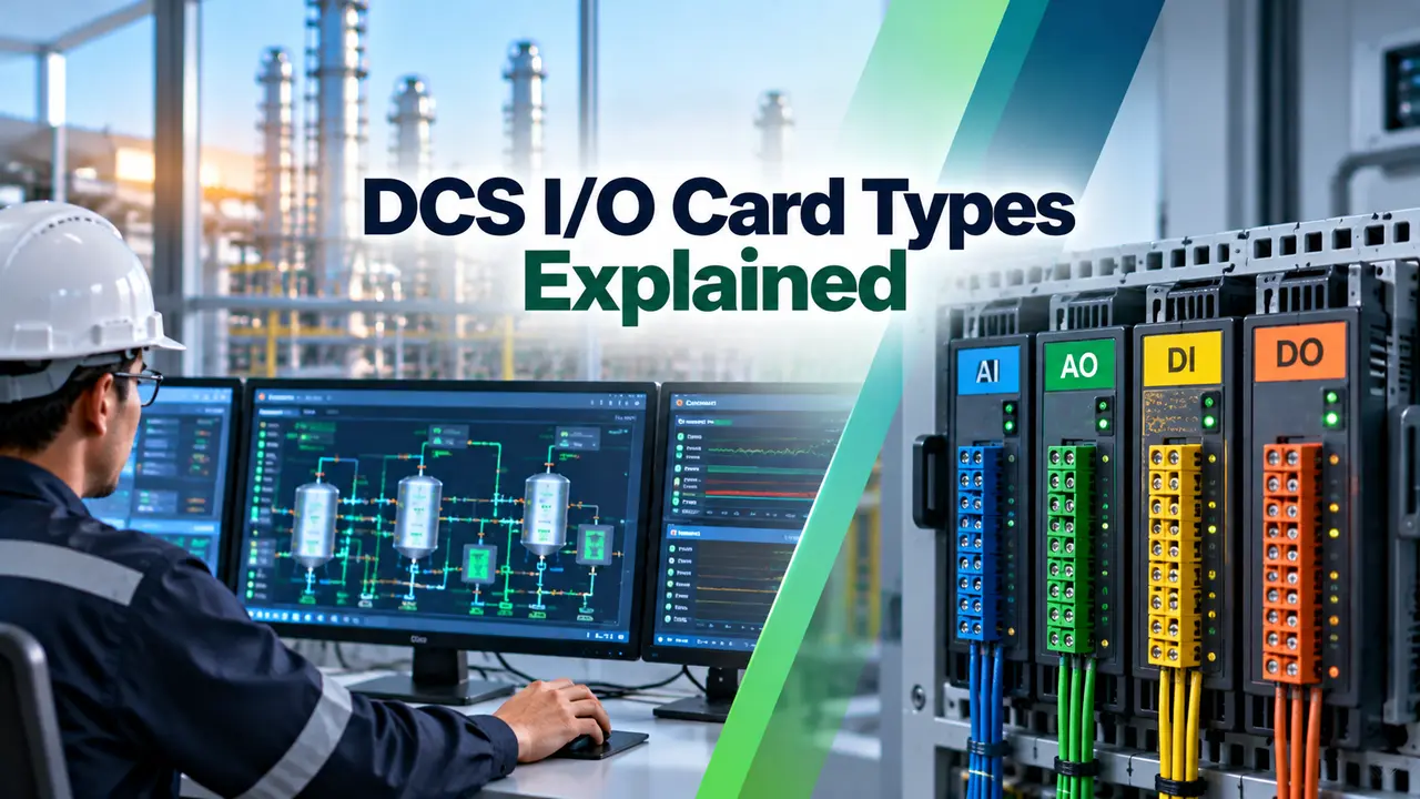
The Four Basic DCS IO Card Types
An analog input card reads a continuously variable signal, most often a 4 to 20 milliamp current loop from a transmitter, converting it into a digital value the controller can use.
An analog output card does the reverse, converting a digital value from the controller into a 4 to 20 milliamp signal that drives a control valve positioner or similar final element.
Digital input and digital output cards handle simple on or off signals, a digital input reads a switch or contact status, while a digital output drives a relay, solenoid, or indicator lamp.
Why Signal Type Determines Card Selection
Choosing the wrong card type for a given field device simply will not work, a transmitter producing a continuous current signal cannot be wired into a card built only to read a contact's open or closed state.
Getting this specification right during the design phase, using an instrument index and I/O list, avoids costly field rewiring once cabinets are already built and installed.
Channel Density and Cabinet Space Planning
Each card supports a fixed number of channels, commonly 8, 16, or 32 depending on the manufacturer and card family, and that count drives how much cabinet space a project ultimately needs.
A higher channel density card lowers cabinet footprint and cabling cost, but a single card failure then affects more field signals at once, so the tradeoff between density and fault isolation is a real design decision, not just a cost exercise.
Cabinet layout also has to account for wiring access, cable tray routing, and the physical reach of field terminations, and a poorly planned cable tray fill can force expensive rework long after the cabinets ship.
A Closer Look at Each Card
| Card Type | Typical Signal | Common Field Device |
|---|---|---|
| Analog input | 4 to 20 mA, sometimes with HART overlay | Pressure, flow, level, temperature transmitters |
| Analog output | 4 to 20 mA | Control valve positioners, VFD speed references |
| Digital input | 24 VDC dry or wet contact | Limit switches, pushbuttons, status contacts |
| Digital output | 24 VDC or relay contact | Solenoid valves, motor starters, lamps |
HART and Smart Signal Handling
Many analog input cards support HART, a digital signal riding on top of the standard current loop, giving access to diagnostic data and configuration parameters beyond the basic measured value itself.
A HART capable card reads both the analog value and the digital HART data over the same two wires, avoiding the need for separate wiring just to access a transmitter's diagnostic information.
Redundant vs Simplex Cards
A simplex card has no backup, if it fails, every signal wired to it is lost until the card is physically replaced, an outcome unacceptable for a critical loop.
A redundant card pairing runs two identical cards simultaneously, with the system automatically switching to the standby unit within milliseconds if the active card fails, keeping the process running uninterrupted.
Card Diagnostics and Fault Reporting
Most modern cards run continuous self diagnostics, checking their own power supply, communication link, and channel circuitry, and reporting a fault to the operator station well before a channel actually stops working correctly.
A card that reports a degraded but not yet failed condition gives maintenance a planned window to swap it, rather than forcing an unplanned shutdown once the channel finally drops out entirely.
Where signals pass through an intrinsically safe barrier ahead of the card, proper intrinsically safe design and correct grounding practice both matter just as much as the card specification itself for reliable readings.
Selecting Cards for a New Project
Dedicated Cards vs Universal I/O
Dedicated Cards
Lower cost per channel, simpler to troubleshoot, but require more spare part variety.
Universal I/O
One spare covers any signal type, at a higher per channel cost than dedicated cards.
Many plants now stock a smaller number of universal cards as spares across the whole facility, accepting the higher unit cost in exchange for dramatically simpler spare parts management.
Wiring Practices That Protect Card Inputs
Field wiring at the card terminal is where most avoidable damage happens, a transient voltage spike from a nearby motor starter or lightning event can ride down a signal cable and destroy an input channel in an instant.
Installing appropriate surge protection at the marshalling cabinet, ahead of the card itself, is a cheap safeguard against that kind of transient damage.
Separating signal cabling from power cabling in the tray, and using shielded twisted pair for analog signals, both reduce the electrical noise that shows up as an unstable or jittery reading at the card.
Digital Fieldbus Alternatives to Point to Point Wiring
Not every signal has to run back to a dedicated I/O card channel, a fieldbus network lets many field devices share a single pair of wires and a single interface card.
This approach trades individual I/O cards for a fieldbus interface card plus segment wiring, cutting cabinet footprint and cabling cost substantially on a project with a large device count.
Maintenance and Spare Parts Strategy
A sound maintenance strategy for DCS I/O card types starts with a spares cabinet stocked against the actual population installed on site, not a generic vendor recommendation that ignores the plant's real signal mix.
Firmware on newer cards can usually be updated without removing the card from the rack, but any firmware change should still go through the same management of change process as a physical hardware swap.
Keeping a simple spreadsheet or database of which card serial number sits in which slot, along with its firmware revision, saves considerable time during a future troubleshooting session or a vendor recall notice.
Common Mistakes to Avoid
Watch: Analog Inputs and Outputs in PLC and DCS
DCS I/O Card Types FAQs
Related Articles on This Site
- DCS Controller Redundancy Types
- DCS Components, ES, OS, AS
- DCS Network Redundancy, Ring, Star, Dual
- HART Loop Resistor in HART Communication
- DCS Fieldbus Integration, HART, Foundation Fieldbus, Profibus PA
External References
What We Learn Today
- The four basic card types are analog input, analog output, digital input, and digital output.
- HART capable cards read both the analog signal and overlaid digital diagnostic data.
- Redundant cards protect critical loops from a single card failure taking down every wired signal.