A displacer transmitter never measures level directly; it weighs a sinker and reads how much lighter the liquid makes it. Once you can turn that buoyant force into span and calibration weights, commissioning and troubleshooting become simple arithmetic.
Every displacer level calculation starts with Archimedes and ends with the weights you hang on the torque arm. This guide covers liquid and interface span, density effects, dry and wet calibration and a solved example with a calculator.
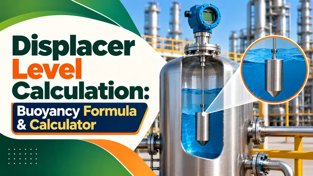
What Is Displacer Level Calculation?
Displacer level calculation finds the buoyant force on a submerged displacer at each level, using Archimedes principle F = ρ × g × V, and turns it into the transmitter span and the calibration weights. The apparent weight sensed by the torque tube is the displacer weight minus that buoyant force, so it falls as the level rises.
- Buoyant force F = ρ × g × V, where V is the submerged volume
- Apparent weight = displacer weight minus buoyant force
- Liquid span force = (ρ liquid minus ρ vapour) × full displacer volume
- Interface span force = (ρ heavy minus ρ light) × full displacer volume
- Dry calibration weight at any level = displacer mass minus buoyancy at that level
This page is a companion to our article on the displacer level transmitter working principle, which explains the hardware. Here we stay with the numbers you need on the calibration sheet.
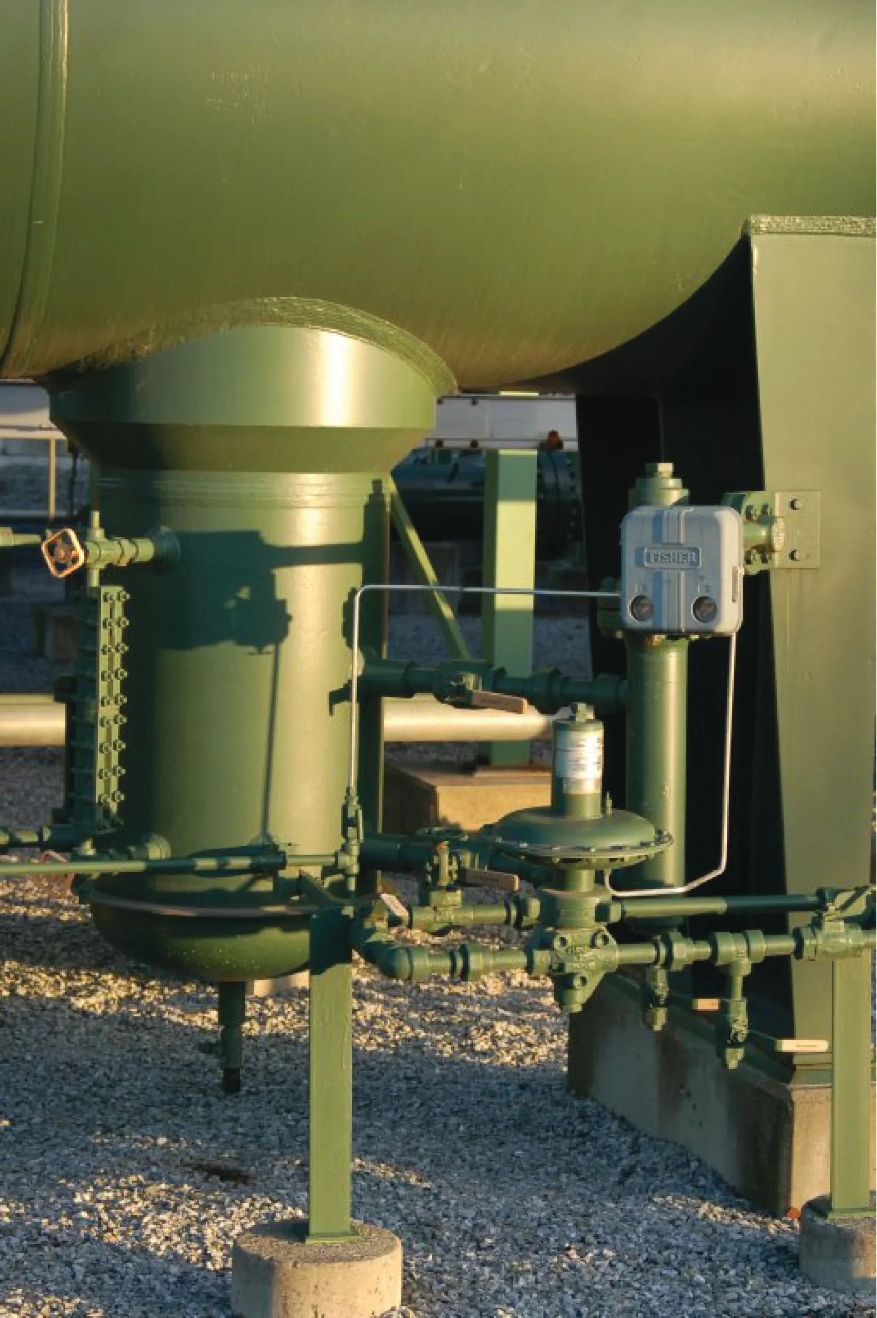
A displacer instrument measures the apparent weight loss of a sealed, weighted displacer hanging in a cage. It also notes that the only fluid property that matters is the density of the process fluid.
Buoyancy Formula Behind Every Displacer
A displacer is heavier than the liquid, so it never floats and it barely moves. The buoyant force changes in direct proportion to the submerged length, which makes the output linear with level for a constant diameter displacer.
V = (π ÷ 4) × d² × h, h = submerged length
Apparent weight = W minus F
Span force = (ρ lower minus ρ upper) × g × (π ÷ 4) × d² × L
Here W is the displacer weight, d its diameter, L its full length and ρ the density in kg/m³. Working in kilograms of mass rather than newtons is convenient, because the calibration weights are read in kilograms too.
Because only density matters, read our guide on specific gravity before you start, and take the operating density, not the density at 15 °C. Static pressure has negligible effect, unlike in DP transmitter level measurement.
The displacer length sets the maximum measuring range, since buoyancy cannot change once the sinker is fully covered. A 356 mm displacer can never measure more than 356 mm of level, whatever the transmitter range.
Displacer Level Calculation for Liquid Level
In liquid level service the upper phase is vapour or gas and the lower phase is liquid. At 0 percent the displacer hangs in vapour, and at 100 percent it is fully covered by liquid.
For most atmospheric tanks the vapour density is small and can be ignored. On high pressure gas separators it can reach tens of kg/m³, so it must be subtracted in the displacer level calculation.
Solved Example: Liquid Level Span and Weights
Take a displacer of 76.2 mm diameter and 356 mm length, close to a 3 x 14 inch size, with an assumed mass of 2.30 kg. The liquid is a hydrocarbon of 850 kg/m³ and the vapour above it is air at 1.2 kg/m³.
Buoyancy at 0 % = 1.2 × 0.0016235 = 0.0019 kg
Buoyancy at 100 % = 850 × 0.0016235 = 1.3800 kg
Span = 1.378 kg = 13.51 N
Hang at 0 % = 2.30 minus 0.0019 = 2.298 kg
Hang at 50 % = 2.30 minus 0.6909 = 1.609 kg
Hang at 100 % = 2.30 minus 1.3800 = 0.920 kg
| Level % | Buoyancy, kg | Weight to Hang, kg | Output, mA |
|---|---|---|---|
| 0 | 0.002 | 2.298 | 4.00 |
| 25 | 0.346 | 1.954 | 8.00 |
| 50 | 0.691 | 1.609 | 12.00 |
| 75 | 1.036 | 1.265 | 16.00 |
| 100 | 1.380 | 0.920 | 20.00 |
This is the full five point table for the sheet, matching a level transmitter 5 point calibration. Note that the weight to hang falls as level rises, because the liquid lifts part of the displacer weight; to turn level into stock, use our tank volume from level calculator.
Weigh the real displacer on a calibrated scale before the job instead of trusting the datasheet. Old displacers pick up deposits or small leaks, and a few grams of error shift the whole calibration.
Interface Displacer Level Calculation
For an interface between two liquids, the displacer must stay fully submerged at all times, with the light liquid above and the heavy liquid below. At 0 percent it sits entirely in the light liquid, and at 100 percent entirely in the heavy liquid.
Buoyancy at 0 % = 850 × 0.0016235 = 1.380 kg
Buoyancy at 100 % = 1000 × 0.0016235 = 1.623 kg
Interface span = 0.244 kg
Hang at 0 % = 0.920 kg, at 100 % = 0.677 kg
The interface span is only 0.244 kg, less than one fifth of the liquid level span, because the two densities are close. A smaller density difference makes the displacer level calculation more sensitive to density errors, so displacers are often made longer or larger for interface duty.
The Control.com textbook works a similar interface case in US units, with liquids of specific gravity 1.10 and 0.850 and a 30 inch displacer. It gets 5.47 lb at the lower range value and 7.08 lb at the upper, and our article on interface level measurement compares other methods.
Both cage nozzles must be submerged in interface service, or the upper phase inside the cage stops matching the vessel. Control.com stresses this point in its displacement level chapter.
Dry Calibration Weights From the Displacer Level Calculation
Dry calibration simulates level by removing the displacer, or isolating the cage, and hanging known weights on the torque arm. The hanging weight equals the apparent weight the displacer would have at that level.
Control.com describes a dry calibration that pulls upward on the displacer with a string and scale, applying a force equal to the full range buoyant force. Smart transmitters also allow the span to be entered as density and displacer volume, but a weight check is still the best proof; for the general method see zero and span adjustments.
Wet Calibration With Water
Wet calibration fills the cage with a test liquid and compares the output with a sight glass. When the process liquid cannot be used, water is common, and the water level is scaled by the density ratio in the displacer level calculation.
100 % process at 850 kg/m³ = 0.85 × 356 = 302.6 mm of water
50 % process = 151.3 mm of water
Fill the cage to 302.6 mm of water and the transmitter should read 100 percent for the 850 kg/m³ service. Use a clear hose or the magnetic level gauge on the cage to read the water height.
For wet calibration, mark the bottom of the displacer on the outside of the cage before you start. All water heights are measured from that mark, not from the bottom nozzle.
Displacer Level Calculation Calculator
For interface service in this displacer level calculation tool, enter the light liquid density as the upper fluid and the heavy liquid as the lower fluid. The tool also warns you if the mass you entered would let the displacer float.
Density Change Effect on Displacer Level Calculation
A displacer is calibrated for one density, so any change in process density shows up as a level error. For liquid level, the indicated level equals the true level multiplied by the ratio of actual to calibrated density.
Calibrated 850, actual 800 kg/m³
True 50 % reads 50 × 0.941 = 47.1 %
A 6 percent density drop gives a 6 percent low reading, which can be enough to trip a low level alarm. DP transmitters share the same problem, as our page on DP level with varying density explains, while radar level transmitters are far less affected.
Torque Tube Materials and Displacer Sizes
The torque tube acts as a torsional spring that holds the displacer, seals the process pressure and passes the rotation to the sensor. Emerson lists N05500 as the standard Fisher 249 torque tube material, with 316 stainless steel, N06600 and N10276 as options.
The same Fisher 249 caged sensor manual notes that N05500 is not recommended for spring use above 232 °C. Its parts list includes displacers of 3 x 14 inch, 2 x 32 inch and 1.5 x 60 inch, which shows how length is traded against diameter.
Troubleshooting a Displacer Level Calculation
| Symptom | Likely Cause | Fix |
|---|---|---|
| Reads low across the range | Density lower than the calibration value | Recalculate span at the real density |
| Stuck at a value | Displacer touching the cage or deposits | Inspect and clean, check alignment |
| Reads 0 % with level present | Displacer leaking and filled with liquid | Weigh the displacer and replace it |
| Interface reads wrong | Upper nozzle not submerged | Check the cage connection layout |
For a wider fault list, use our level transmitter troubleshooting guide. If the service keeps changing density, compare other options in types of level transmitters.
- Simple, proven physics.
- Works at high pressure and temperature.
- Good for interface and density.
- Sensitive to density changes.
- Range limited by displacer length.
- Moving parts need maintenance.
Fisher 249 Caged Displacer Sensors Manual PDF
Video: Magnetrol Liquid Level Displacement Transmitter
Displacer Level Calculation FAQ
Multiply the liquid density by gravity and by the submerged volume of the displacer. For a cylinder the volume is π times d squared times the covered length divided by 4.
In kilograms, just multiply density in kg/m³ by volume in cubic metres. A 1.6235 litre displacer in 850 kg/m³ liquid carries 1.38 kg of buoyancy.
At each level, hang the displacer mass minus the buoyancy at that level. At 0 percent this is almost the full displacer mass in vapour.
At 100 percent it is the mass minus the full buoyancy of the covered displacer. Intermediate points such as 25, 50 and 75 percent are found by straight line interpolation between the two values.
For interface, the displacer stays fully submerged and the span uses the density difference of the two liquids. The light liquid sets 0 percent and the heavy liquid sets 100 percent.
Because the density difference is small, the span force is much smaller. That makes interface calibration more sensitive to errors in the density values you use.
Wet calibration fills the cage with a real liquid and compares the output with a sight glass. Dry calibration simulates the buoyancy by hanging known weights on the torque arm.
Dry calibration is faster and needs no liquid handling in the field. Wet calibration proves the whole system, including the displacer and the cage, in one test.
The buoyant force is proportional to density, so the same level gives less force in a lighter liquid. The transmitter then reads a lower level than the true one.
The error is proportional to the density ratio. So a liquid that is 6 percent lighter than the calibration value will read about 6 percent low at every level.
The torque tube is a hollow shaft that twists slightly as the apparent weight of the displacer changes. It also seals the process from the transmitter head.
The small rotation is passed to a sensor that converts it into the output signal. Its material, such as N05500 or 316 stainless steel, is chosen for temperature, pressure and corrosion in each service.
Related Articles
- Displacer Level Transmitter Working Principle
- Interface Level Measurement
- Level Transmitter 5 Point Calibration
- DP Level Measurement With Varying Density
- Types of Level Transmitters
External References
- Fisher 249 Caged Displacer Sensors Instruction Manual, Emerson
- Displacement Level Measurement, Control.com Textbook
- Archimedes Principle, Wikipedia
What We Learn Today
- A displacer level calculation uses F = ρgV to find the buoyancy at each level, and the torque tube senses the displacer weight minus that force.
- Liquid span uses liquid minus vapour density, while interface span uses heavy minus light liquid density over the full displacer volume.
- Dry calibration weights equal displacer mass minus buoyancy at each level, and wet calibration with water scales height by the density ratio.