
A valve that controls well at full load can hunt, stick or slam shut when the plant runs at a fraction of its design flow. Understanding how far a valve can really turn down, inside its real piping system, keeps every operating point smooth and stable.
Rangeability tells you how small a flow a control valve can still handle accurately compared with its largest flow. The catalogue number is only the start, because pressure drop, sizing and trim decide what you actually get in the plant.
What Is Control Valve Rangeability?
Control valve rangeability is the ratio of the largest to the smallest flow coefficient over which a valve still follows its specified flow characteristic within stated limits. It is written as Cv max ÷ Cv min, and the control valve flow coefficient Cv is the number on which the whole idea rests.
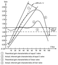
The chart above, from a Control Global article by Béla Lipták, shows how a real equal percentage valve departs from its theoretical curve at both ends of travel. That departure sets the useful range, and it links directly to the flow characteristics of control valves.
Inherent vs Installed Control Valve Rangeability
Inherent control valve rangeability is measured by the manufacturer on a test rig with a constant pressure drop across the valve. Catalogues often quote 50 to 1 for globe valves and higher figures for characterised ball valves, yet these numbers assume ideal test conditions.
Installed control valve rangeability is what you get in the plant, where pump curves, pipe friction and fittings change the valve pressure drop as flow changes. At high flow the line losses rise and the valve sees less pressure drop, which is why pressure drop in pipes must be calculated before sizing.
Lipták reports, quoting Les Driskell, that an equal percentage valve stays within 25 percent of its theoretical characteristic only between about 5 and 70 percent of its Cv. That gives a practical control valve rangeability of roughly 14 to 1, far below many catalogue claims.
Rangeability Formula and Valve Lift
For an ideal equal percentage trim, the relative Cv changes by the same percentage for every equal step of travel. The lift needed for any required Cv therefore follows a simple logarithmic relation with the inherent rangeability R.
Equal percentage lift x = 1 + ln(Cv required ÷ Cv rated) ÷ ln(R)
Required turndown = Cv at max flow ÷ Cv at min flow
Example: rated Cv = 100, R = 50
Cv needed at max flow = 70, at min flow = 5
Lift at max = 1 + ln(0.70) ÷ ln(50) = 1 + (minus 0.357 ÷ 3.912) = 0.909, so 90.9 %
Lift at min = 1 + ln(0.05) ÷ ln(50) = 1 + (minus 2.996 ÷ 3.912) = 0.234, so 23.4 %
Required turndown = 70 ÷ 5 = 14.0 to 1
For control valve rangeability, the example shows a valve that just fits, since the minimum flow sits at 23.4 percent lift and the maximum at 90.9 percent. A maximum lift above 90 percent leaves little room for upsets, so many engineers would pick a slightly larger trim, as explained in control valve sizing basic requirements.
Equal Percentage Lift and Turndown Calculator
If the calculator shows a minimum lift below about 10 percent, the valve is oversized for the low flow case. A negative result, printed as minus, means the required Cv lies below the theoretical minimum of the trim and the valve cannot control there at all.
Second Worked Example: Installed Rangeability
Flow through a valve is Q = Cv × √(ΔP ÷ SG), so the installed range depends on both Cv and the pressure drop at each end. At maximum flow the valve drop is lowest, while at minimum flow the pump pushes harder and the valve drop is highest.
Inherent R = 50
Valve ΔP at max flow = 1 bar, at min flow = 4 bar
√(1 ÷ 4) = 0.5
Installed rangeability = 50 × 0.5 = 25 to 1
Half of the inherent control valve rangeability is lost purely to the change in pressure drop across the valve. Low valve authority makes this worse, and it also bends the installed curve, so the same check belongs in every control valve selection review.
Ask the process engineer for the valve pressure drop at minimum, normal and maximum flow, not only at normal flow. Without the minimum flow case you cannot check the low lift end at all.
Rangeability vs Turndown: Know the Difference
Rangeability describes the valve itself, while turndown describes what the process needs, namely maximum required flow divided by minimum required flow. The same words appear for meters, as in turndown ratio of flow meters, and the idea is similar.
| Term | Defined By | Formula | Typical Values |
|---|---|---|---|
| Inherent rangeability | Valve test at constant ΔP | Cv max ÷ Cv min | 30 to 1 up to 300 to 1 |
| Installed rangeability | Valve in its real system | R × √(ΔP high flow ÷ ΔP low flow) | Often half of inherent |
| Process turndown | Plant operating needs | Q max ÷ Q min | 5 to 1 up to 50 to 1 |
| Practical range | Usable lift band | Cv at 70% ÷ Cv at 10% lift | About 14 to 1, Lipták |
A valve is suitable only when its installed control valve rangeability is comfortably larger than the process turndown. Orifice meters have a similar square root limit, explained in orifice flowmeter rangeability, so check the meter and the valve together.
Trim Types and Their Usable Range
Each step of lift raises Cv by a fixed percentage of the current Cv.
Cv rises in direct proportion to travel.
V notch or segmented ball shapes the opening.
Rotary disc with contoured profile for control.
Rotary valves usually claim a higher inherent rangeability than globe valves, but their characteristic is often steep near closure. Compare options in butterfly valve vs ball valve for control and in control valve trim types before you trust a catalogue figure.
Lipták states that no standard control valve can handle a process rangeability beyond about 20 to 1, although special trims improve on this. Wider ranges are normally met with two valves in parallel or split range.
Why Valves Struggle at Low Lift
Near the seat the clearance between plug and seat ring is tiny, so small dimensional errors produce large relative Cv errors. Packing friction and actuator deadband also matter more when every movement must be very small.
The result is stick slip, where the plug jumps instead of moving smoothly, and the loop starts to cycle. A valve positioner helps, but it cannot fix a valve that is simply far too large for the low flow.
7 Practical Rules for Control Valve Rangeability
Split Range and Parallel Valve Alternatives
When process turndown exceeds the control valve rangeability of one valve, a small valve and a large valve can share the controller output. In split range control, the small valve opens over the first part of the signal and the large valve over the rest.
In the DCS, mark the handover point clearly on the faceplate and trend both valve positions together. Operators then understand why the loop behaves differently around the middle of the output range.
Control Valve Rangeability Selection Checklist
- Minimum, normal and maximum flow cases with matching pressures are available.
- Required Cv at each case is calculated, not estimated.
- Minimum flow lift is at least 10 percent on the chosen trim.
- Maximum flow lift is below about 90 percent.
- Installed rangeability exceeds the process turndown with margin.
- Seat leakage class is confirmed for the low flow position.
- Cavitation, noise and outlet velocity are checked at every case.
Where Wide Rangeability Matters Most
- Stable control from startup to full load.
- Less wear at the seat and plug.
- Lower risk of cavitation at low lift.
- Fewer manual interventions by operators.
- Catalogue values are optimistic for real piping.
- Wide range trims can cost more.
- Split range adds tuning and handover issues.
- Accurate process data is needed for every case.
Troubleshooting Poor Low Flow Control
If a loop cycles only at low load, trend valve position and flow together and check whether the valve sits below 10 percent lift. A slow sawtooth in position with steps in flow points to stiction, discussed in control valve troubleshooting.
Lipták recommends that a valve should operate between about 10 and 70 percent opening across its minimum and maximum flows. That simple band is one of the quickest field checks of control valve rangeability.
Fisher Control Valve Handbook PDF
Video on Rangeability and Controllability
Control Valve Rangeability FAQ
It is the ratio of the largest to the smallest flow coefficient over which a valve keeps its specified characteristic. It is written as Cv max divided by Cv min.
The Fisher handbook gives a simple example of 100 to 1. Such a valve still controls well when flow rises to 100 times its minimum controllable value.
Inherent rangeability is measured on a test rig with a constant pressure drop across the valve. Installed rangeability includes the real change in pressure drop between low and high flow.
Because the valve drop usually falls as flow rises, the installed value is lower. Multiply the inherent value by the square root of the drop ratio to estimate it.
Lipták, quoting Les Driskell, reports that it stays within 25 percent of its ideal curve between about 5 and 70 percent of Cv. That corresponds to a practical range of about 14 to 1.
Catalogue figures of 50 to 1 or more assume ideal conditions. Use the practical figure when you check a real process turndown.
Rangeability is a fixed property of the valve body, plug and seat. Turndown is the ratio of maximum to minimum flow that the process actually needs.
A valve suits the duty only when its installed rangeability is larger than the process turndown. Leave a sensible margin for uncertainty in the process data and future changes.
Near the seat, small plug tolerances cause large relative Cv errors and packing friction makes every movement jerky. The loop then cycles steadily and the trim erodes quickly.
High velocity through the tiny opening can also start cavitation in liquid service. Size the valve so that minimum flow sits comfortably above about 10 percent lift.
Use them when the process turndown is larger than one valve can handle with good, stable control. A small valve covers low demand and a large valve takes over for high demand.
The handover point needs careful tuning so loop gain stays similar. Trend both valve positions together during commissioning to confirm a smooth and bumpless transfer.
A positioner improves accuracy and reduces the effect of friction at small lifts. It helps a correctly sized valve make fine, repeatable movements near its seat ring.
However, it cannot change the trim geometry or the installed pressure drop. A badly oversized valve still has poor low flow control even with the best smart positioner.
Related Articles
- Control Valve Flow Coefficient
- Flow Characteristics of Control Valves
- Split Range Control Working Principle
- Control Valve Sizing Basic Requirements
- Turndown Ratio of Flow Meters
External References
- Control Valve Handbook Fifth Edition, Emerson Fisher
- Rangeability of Equal Percentage Control Valves, Control Global
- Control Valve, Wikipedia
What We Learn Today
- Control valve rangeability is Cv max divided by Cv min, and the installed value falls as the valve pressure drop changes between low and high flow.
- An equal percentage valve gives a practical range of about 14 to 1 in real plants, according to Lipták, even when catalogues quote 50 to 1.
- Keep minimum flow above about 10 percent lift and use split range or parallel valves when process turndown exceeds what one valve can handle.