Capacitors combine in the opposite way to resistors, and that one fact explains most design mistakes in filter and DC bus banks. Here we work through the formulas, voltage sharing, balancing resistors and ESR with real numbers.
Series connection raises the voltage rating but lowers capacitance, while parallel connection adds capacitance at the same voltage. We cover both with solved examples, ESR, energy and a calculator.
What Are Capacitors in Series and Parallel?
The topic of capacitors in series and parallel describes the two basic ways of joining capacitors: end to end so the same charge flows through each, or side by side so each sees the same voltage. In series the total is found from 1/C = 1/C1 + 1/C2 + ..., while in parallel the total is simply C = C1 + C2 + ...
| Property | Series connection | Parallel connection |
|---|---|---|
| Equivalent capacitance | 1/C = 1/C1 + 1/C2 + ... | C = C1 + C2 + ... |
| Result vs smallest part | Less than the smallest | More than the largest |
| Common quantity | Same charge Q | Same voltage V |
| Voltage rating | Adds, if shared evenly | Same as the lowest rated part |
| Equivalent ESR | ESR values add | ESR values combine like parallel resistors |
| Typical use | High voltage DC bus banks | Bulk storage, low ESR filters |
Notice that the rules are the mirror image of resistor rules described in series vs parallel circuits. The reason lies in what capacitance means, the charge stored per volt, which is covered in what is capacitance.
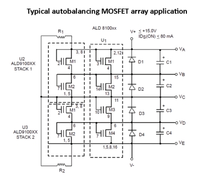
The schematic shows a stack of series cells with a balancing device across each one, a layout we will explain later in this article. Every high voltage capacitor bank you see in a drive or UPS uses some version of this idea.
Capacitors in Series Formula and Voltage Sharing
In a series string the same charging current flows through every capacitor, so every part holds the same charge Q. Since V = Q/C for each part, the voltage splits in inverse proportion to capacitance, and the smallest capacitor takes the largest voltage.
1/Cs = 1/C1 + 1/C2 + 1/C3
Two parts only: Cs = C1 × C2 ÷ (C1 + C2)
Same charge: Q = Cs × V
Voltage on each part: Vn = Q ÷ Cn
This inverse sharing is the key safety point of capacitors in series and parallel. If one 10 µF part sits in series with a 47 µF part across 50 V, the small part gets about 41 V and the large one only about 9 V, even though both may be rated 35 V.
Two equal capacitors in series give exactly half the capacitance of one part. Three equal parts give one third, which is why series strings need larger individual values to reach the target.
The sum of the individual voltages always equals the applied voltage, a direct result of Kirchhoff voltage law. You can also see the series string as a capacitive version of the voltage divider rule, except that the bigger part takes the smaller share.
Capacitors in Parallel Formula and Ripple Sharing
Parallel connection puts the same voltage on every capacitor, so the charges simply add and so do the capacitances. This is the normal way to build bulk storage in power supplies and to place several decoupling capacitors near a processor.
Cp = C1 + C2 + C3
Same voltage on every part
Charge on each part: Qn = Cn × V
Voltage rating = lowest rated part
In a parallel bank the ripple current does not share by capacitance, it shares by impedance, and at switching frequencies that means mostly by ESR. A part with low ESR takes more ripple and runs hotter, which is a common cause of early failure in mixed banks.
Never mix ceramic and electrolytic capacitors in parallel and assume they share ripple evenly. The ceramic part carries almost all high frequency current, so check its ripple rating and its real value under bias using MLCC DC bias capacitance loss data.
Identical parts in series, voltage shared evenly in theory.
Identical parts side by side for higher capacitance.
Parallel groups joined in series for both voltage and capacitance.
Different values in parallel to cover a wide frequency band.
Each capacitor technology also changes the rules a little, because tolerance, leakage and ESR differ widely, as compared in capacitor types explained. The working of the dielectric itself is explained in capacitor working principle.
Balancing Resistors for Series Capacitors
In theory equal capacitors share voltage equally, but in DC service the sharing is set by leakage current, not by capacitance. Abracon explains in its supercapacitor balancing note that tolerances such as minus 10 to plus 30 % and differences in leakage resistance can push one cell above its rating.
The simple cure is a resistor across each capacitor, sized so the resistor current swamps the leakage difference. Power Electronic Tips describes this passive method and notes that it fails if the parts are poorly matched, so matching cells first still matters.
V1 = V/2 + R × ΔI_leak ÷ 2
Example: V = 700 V, R = 100 kΩ, ΔI_leak = 0.1 mA
V1 = 350 + 5 = 355 V
Power per resistor = 350² ÷ 100000 = 1.23 W
A lower resistor value holds the sharing tighter but wastes more power, while a higher value saves power but lets the imbalance grow. Always check the wattage and voltage rating of each resistor with the guidance in resistor power rating and derating.
- Very low cost and simple
- No active parts to fail short
- Also discharges the bank at power off
- Works for electrolytic and supercapacitor stacks
- Constant power loss and heat
- Slow to correct large imbalances
- Needs high voltage resistor ratings
- Not efficient for battery powered systems
Bleeder resistors across a series bank do two jobs at once. They balance the voltage while running and they safely discharge the capacitors after the drive or supply is switched off.
Equivalent ESR and Stored Energy
Equivalent series resistance adds in a series string and divides in a parallel bank, the same as ordinary resistors. Two parts with 50 mΩ and 80 mΩ in parallel give about 31 mΩ, which is why designers use several small parts instead of one big one, a topic covered in capacitor ESR.
Series: ESR_total = ESR1 + ESR2
Parallel: 1/ESR_total = 1/ESR1 + 1/ESR2
50 mΩ parallel 80 mΩ = 30.8 mΩ
Energy: E = ½ × C × V²
Stored energy grows with the square of voltage, so a series bank at high voltage can store much more energy than a parallel bank of the same parts at low voltage. Two 4700 µF, 450 V parts in series give 2350 µF, and at 700 V that string stores ½ × 0.00235 × 700² ≈ 576 J.
When you measure a series bank with an LCR meter, discharge it fully first and measure each part on its own. A single weak part hides easily inside the total reading of a large string.
Capacitors in Series and Parallel Calculator
Enter three capacitance values in microfarads and the applied voltage to see the series and parallel totals plus how the voltage splits in series. The default values match the solved example below.
1/Cs = 1/10 + 1/22 + 1/47 = 0.16673
Cs = 6.00 µF
Q = 6.00 µF × 50 V = 299.9 µC
V1 = 299.9 ÷ 10 = 29.99 V
V2 = 13.63 V, V3 = 6.38 V
Parallel Cp = 10 + 22 + 47 = 79 µF
The 10 µF part takes almost 30 V, which is 60 % of the supply, while the 47 µF part sees only about 6 V. This is exactly why unequal capacitors in series must be rated for their own share, not for an average.
Once your bank is sized, check its life with the capacitor lifetime calculator, because ripple heating in a parallel bank shortens life quickly. Large supercapacitor stacks follow the same rules, as shown in supercapacitor working principle.
Applications and Field Tips
In the AC power world the same parallel rule sizes power factor banks, covered in capacitor bank sizing. In small signal work, capacitors in series and parallel are often combined to trim the corner of an RC low pass filter.
- Use the series formula for strings and the sum for parallel banks
- Check each series part against its own voltage share
- Fit balancing resistors on any DC series string above a few volts
- Rate resistors for both power and voltage
- Match capacitor values and batches in series strings
- Measure cell voltages after warm up during commissioning
The Abracon note explains how capacitance tolerance, leakage and ESR each affect sharing at different stages of charge and discharge. Read it together with our guide on how to test a capacitor before you service an old bank.
Capacitors in Series and Parallel FAQ
For series connection use 1/C = 1/C1 + 1/C2 + 1/C3, so the total is always smaller than the smallest part. For parallel connection simply add the values, so the total is larger than the largest part.
These rules are the reverse of resistor rules. Remember them by thinking about plate area and plate spacing of the combined capacitor.
Yes, every capacitor in a series string carries the same charge, because the same current flows through each part for the same time. The voltage on each part is that charge divided by its own capacitance.
This is why the smallest capacitor takes the largest voltage. It must be rated for that higher share rather than the average value.
The main reason is to reach a working voltage that one part cannot handle alone, such as a 700 V drive DC link built from 450 V parts. Series strings are also used to make an odd value from standard parts.
The price is a lower total capacitance. Designers usually add parallel groups to win the capacitance back.
In DC service the voltage sharing is controlled by leakage current, which varies widely from part to part. Without resistors one capacitor can drift above its rated voltage and fail.
A resistor across each part sets a current that is much larger than the leakage difference. The resistors also discharge the bank safely after power is removed.
Treat the ESR values like resistors in parallel, so 1/ESR equals the sum of 1/ESR for each part. Two parts of 50 and 80 milliohms give about 31 milliohms in total, lower than either part.
For series strings the ESR values simply add up. This is why parallel banks are used to get low ESR in switching supplies.
Yes, capacitance adds directly in parallel because the effective plate area grows while the voltage stays the same. Three parts of 10, 22 and 47 µF in parallel give 79 µF in total, which is simple addition.
The voltage rating of the bank equals the lowest rated part. Check every part before you connect them across the supply.
Related Articles
- Capacitor Working Principle
- Capacitor ESR Explained
- Series vs Parallel Circuits
- Supercapacitor Working Principle
- How Decoupling Capacitors Work
External References
- Abracon: Supercapacitors Balancing Basics and Techniques (PDF)
- Power Electronic Tips: Fundamentals of Supercapacitor Balancing
- Wikipedia: Series and Parallel Circuits
What We Learn Today
- For capacitors in series and parallel, series uses 1/C = 1/C1 + 1/C2 and parallel simply adds values, the reverse of resistor rules.
- Series parts carry the same charge, so the smallest capacitor takes the largest voltage and DC strings need balancing resistors across each part.
- ESR adds in series and divides in parallel, while stored energy follows half C V squared, so high voltage series banks store much more energy.