Every metre of copper between a Pt100 and its transmitter adds resistance, and the instrument reads it as extra temperature. We work out that error, show how 3 wire and 4 wire circuits remove it, and walk through what to check when a reading is high.
Lead resistance is the most common reason a field RTD reads a few degrees high. Here you get the exact formula, a solved example and the numbers to size your cable so the error stays inside the sensor tolerance.
What error does RTD lead wire resistance cause in a Pt100?
RTD lead wire resistance adds directly to the sensor reading in a 2 wire circuit, so the error in °C equals 2 × Rlead ÷ 0.385 for a Pt100. One ohm of total loop resistance therefore reads about 2.6 °C high. For example, 100 m of 0.5 mm² copper has 3.6 Ω per lead, which adds 7.2 Ω and an error near 18.7 °C, while 3 wire and 4 wire circuits cancel most of it.
What Is RTD Lead Wire Resistance?
RTD lead wire resistance is the resistance of the copper conductors that connect a resistance temperature detector to the transmitter, PLC card or meter. Because an RTD reports temperature as resistance, the instrument cannot tell lead ohms from sensor ohms unless the wiring scheme separates them.
- A Pt100 changes by about 0.385 Ω per °C between 0 and 100 °C (alpha 0.00385 as per IEC 60751).
- 2 wire error in °C = 2 × Rlead ÷ 0.385, so 1 Ω of loop resistance reads about 2.6 °C high.
- 3 wire circuits cancel lead resistance only when all leads match; the residual equals the mismatch.
- 4 wire circuits remove lead resistance from the measurement almost completely.
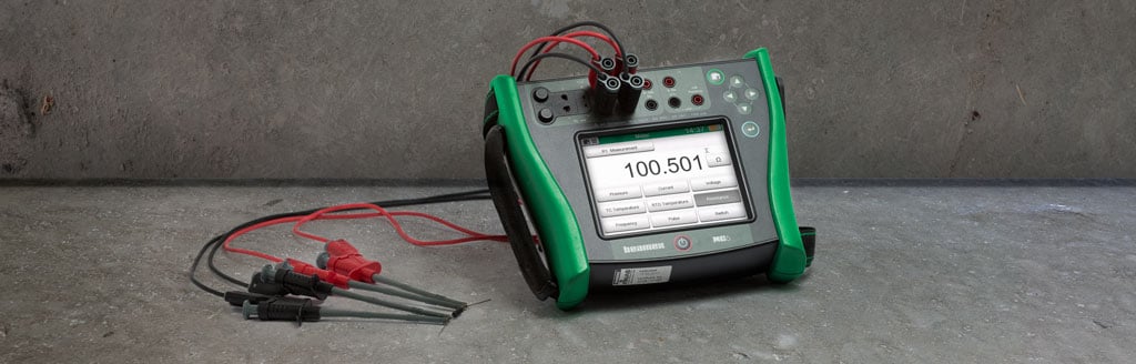
Beamex explains in its resistance measurement guide that a 2 wire connection measures the element plus the lead and contact resistances, so the result is always too high.
Texas Instruments notes in its Basic Guide to RTD Measurements that in a 2 wire circuit the lead resistance cannot be separated from the RTD resistance at all. That is why 2 wire sensors are kept for short runs or for transmitters mounted in the sensor head.
How Does Lead Resistance Cause RTD Error?
Lead resistance causes error because the excitation current flows through the leads as well as the element, so the voltage the instrument measures includes the drop across the copper. The instrument converts that extra voltage into extra degrees, so the reading comes out high.
Error (°C) = (RL1 + RL2) ÷ 0.385
Pt100 rule: 1 Ω of leads ≈ 2.6 °C
The three wiring schemes handle the leads very differently, and our 2 wire, 3 wire and 4 wire RTD page covers the circuit diagrams in detail. Below we look at how many ohms of error each scheme leaves behind.
Both leads sit in series with the element, so all rtd lead wire resistance appears as temperature error.
A third lead lets the transmitter subtract one lead from the other, cancelling resistance when leads match.
Two leads carry current and two sense voltage with almost no current, so lead drop is ignored.
In a 3 wire bridge or transmitter input the compensation works only if the two current carrying leads have the same resistance. Texas Instruments states this assumption plainly, and Minco notes that it matches RTD leads within 5 percent so the residual stays small.
When you replace a damaged 3 wire cable, never join a new cable to an old one on only two cores. Splice all three cores with the same size and length or the lead balance is lost.
How to Calculate RTD Lead Wire Resistance Error
To calculate the error, find the resistance of one lead from cable length and conductor resistance, then divide the uncompensated part by the sensor sensitivity. For a Pt100 the sensitivity is 0.385 Ω per °C, and for a Pt1000 it is 3.85 Ω per °C.
This solved example uses the same numbers you will find as defaults in the calculator below. The cable is a 100 m run of 0.5 mm² copper, which IEC 60228 lists at about 36 Ω per km for a plain copper conductor.
2 wire: 2 × 3.60 = 7.20 Ω
2 wire error = 7.20 ÷ 0.385 = 18.70 °C
3 wire, 5 % mismatch: 0.18 Ω ÷ 0.385 = 0.47 °C
4 wire: about 0 °C
To convert corrected ohms into temperature, use our RTD resistance to temperature calculator. It handles Pt100 and Pt1000 values.
Change the sensitivity to 3.85 to see the same cable on a Pt1000, and the error falls by a factor of ten. You can also cross check the result with this online lead wire error tool before you finalise a cable schedule.
| Copper size | Ω per km | One lead, 100 m | 2 wire Pt100 error | 3 wire, 5 % mismatch |
|---|---|---|---|---|
| 0.5 mm² | 36.0 | 3.60 Ω | 18.70 °C | 0.47 °C |
| 0.75 mm² | 24.5 | 2.45 Ω | 12.73 °C | 0.32 °C |
| 1.0 mm² | 18.1 | 1.81 Ω | 9.40 °C | 0.24 °C |
| 1.5 mm² | 12.1 | 1.21 Ω | 6.29 °C | 0.16 °C |
| AWG 22 | 52.9 | 5.29 Ω | 27.48 °C | 0.69 °C |
| AWG 18 | 20.9 | 2.09 Ω | 10.86 °C | 0.27 °C |
Which Is Better: 2 Wire, 3 Wire or 4 Wire RTD?
A 4 wire RTD gives the best accuracy, a 3 wire RTD is the practical choice for most plant wiring, and a 2 wire RTD is fine only when the transmitter sits on the sensor head.
| Point | 2 Wire | 3 Wire | 4 Wire |
|---|---|---|---|
| Lead error | Full 2 × Rlead | Only the mismatch | Practically none |
| Typical use | Head mount, short runs | Field to marshalling | Labs, reference probes |
| Effect of ambient | Large | Small | Negligible |
| Cost | Lowest | Moderate | Highest |
- Cancels most rtd lead wire resistance with only one extra core.
- Supported by almost every temperature transmitter and RTD input card.
- Good balance of cable cost and accuracy for runs up to a few hundred metres.
- Residual error grows with any lead mismatch or loose terminal.
- Not suitable for reference grade work where 4 wire is expected.
For a wider look at terminal arrangements and colour codes, see our guide to RTD sensor connections and the notes on cable colour codes for field instruments.
Beamex points out that the 3 wire error can be positive or negative, depending on which lead has the higher resistance. So a damaged 3 wire cable can also make the reading drift below the true value.
How Do Cable Length and Wire Gauge Change the Error?
The error from rtd lead wire resistance grows in direct proportion to cable length and falls as the conductor gets thicker, because lead resistance equals length times resistance per km. Doubling the run doubles the 2 wire error, while moving from 0.5 mm² to 1.5 mm² cuts it to about one third.
Ambient temperature matters too, because copper resistance rises by about 0.393 percent per °C. A 2 wire run of 100 m at 0.5 mm² that warms by 20 °C in the afternoon sun gains roughly 0.57 Ω across both leads, which adds about 1.5 °C of drift.
If the cable must be very long, convert the signal near the sensor with a head mount temperature transmitter and send 4 to 20 mA instead. Our article on the 4 to 20 mA current loop explains why current is immune to wire resistance.
Keep RTD cables in a separate tray from motor power cables and use shielded twisted pair cable with the screen earthed at one end only.
Why Does My RTD Read High? Troubleshooting Lead Errors
An RTD usually reads high because of uncompensated lead resistance, a loose or corroded terminal, or a 3 wire cable with unequal cores.
| Symptom | Likely cause | Field check |
|---|---|---|
| Steady offset of several °C | 2 wire on a long run | Measure loop resistance with leads shorted at the head |
| Offset on 3 wire only | Lead mismatch or bad splice | Compare resistance of each core end to end |
| Reading jumps or drifts | Loose or oxidised terminal | Tighten and clean terminals, recheck contact ohms |
| Upscale or downscale alarm | Open lead or element | Check burnout setting and continuity of each core |
For the full bench procedure, follow our step by step guide on how to test an RTD Pt100 with a multimeter. If the transmitter drives to a fixed value on a broken core, the burnout function is doing its job and the cable needs repair.
- Confirm transmitter input is configured for the actual number of wires.
- Measure each core end to end and record the values on the loop sheet.
- Make sure all three cores of a 3 wire run are the same size and length.
- Check insulation resistance between cores and to earth before energising.
Self heating is another small source of high readings that people confuse with lead error, and you can read about it in our note on RTD self heating error. Compare both against the allowed band in RTD tolerance classes of IEC 60751 before blaming the sensor.
How Do You Compensate Lead Resistance in the Field?
You compensate lead resistance by choosing 3 wire or 4 wire wiring, by entering a lead offset in the transmitter, or by moving the transmitter close to the sensor.
Most smart transmitters let you trim this during commissioning, and our guide on temperature transmitter wiring shows where each core lands. After any wiring change, repeat the checks in the Pt100 RTD calibration guide so the loop sheet reflects the final state.
The Calibration Academy video below shows why a 3 wire RTD reads closer to the true value than a 2 wire one.
For the electronics behind each scheme, the Texas Instruments application note is the best free reference.
Free Tools for RTD Calculations
Once you know the lead error, these free tools take you through the remaining conversions and checks. The Callendar Van Dusen calculator is useful when you work above 100 °C, where the simple 0.385 slope starts to drift.
RTD Lead Wire Resistance FAQ
RTD lead wire resistance is the ohmic value of the copper cores between sensor and instrument, and it adds directly to the reading. On a Pt100 every ohm left uncompensated shows as about 2.6 °C of extra temperature.
That is enough to push a sensor outside its Class B tolerance quickly.
Multiply one way length in metres by conductor Ω per km and divide by 1000 to get one lead. For 100 m of 0.5 mm² copper that gives 3.60 Ω per lead.
In 2 wire mode double it to 7.20 Ω and divide by 0.385, which gives 18.70 °C of error.
A 2 wire RTD carries the full resistance of both leads into the reading, while a 3 wire RTD subtracts one lead from the other. With 100 m of 0.5 mm² cable the error falls from 18.70 °C to about 0.47 °C at 5 percent mismatch.
That is why 3 wire is the plant standard.
A 4 wire RTD removes almost all lead error because the voltage sense leads carry nearly zero current. Texas Instruments describes it as the most accurate configuration for this reason.
Small errors from thermal EMF at junctions and from the instrument itself still remain, but lead length no longer matters.
A 3 wire RTD reads high when its current carrying cores have unequal resistance from a splice, a loose terminal or mixed cable sizes. Measure each core end to end and the difference shows the residual error.
Each 0.1 Ω of mismatch on a Pt100 equals about 0.26 °C.
For runs above about 30 m use 3 wire cable of at least 1.0 mm², or 4 wire for narrow span or custody duty. On 100 m of 1.0 mm² copper, 2 wire still gives 9.40 °C error.
For very long runs a transmitter near the sensor sending 4 to 20 mA is the best answer.
Related Articles
- Difference Between 2 Wire RTD, 3 Wire RTD and 4 Wire RTD
- RTD Sensor Connections
- How to Test an RTD Pt100
- RTD Self Heating Error
- Temperature Transmitter Wiring
External References
- Texas Instruments: A Basic Guide to RTD Measurements (PDF)
- Beamex: Resistance measurement, 2, 3 or 4 wire connection
- Wikipedia: Resistance thermometer
What We Learn Today
- RTD lead wire resistance adds directly to a 2 wire Pt100 reading, so every ohm of uncompensated copper shows as about 2.6 °C of error.
- A 3 wire circuit cancels matched leads and leaves only the mismatch, while a 4 wire circuit ignores lead resistance almost completely in practice.
- Calculate one lead as length times Ω per km divided by 1000, then divide the uncompensated ohms by 0.385 to get the error.