
A healthy Pt100 gives a predictable resistance at every temperature, so a simple ohm reading tells you a lot about the sensor. This field guide shows the readings to expect, the checks to run on every wire and the faults each reading points to.
Here is how to test an RTD: a Pt100 is checked by isolating it, measuring the element and lead resistances with a multimeter and comparing the result with the standard resistance table. This guide adds the insulation test, a fault table, a calculator and a solved example.
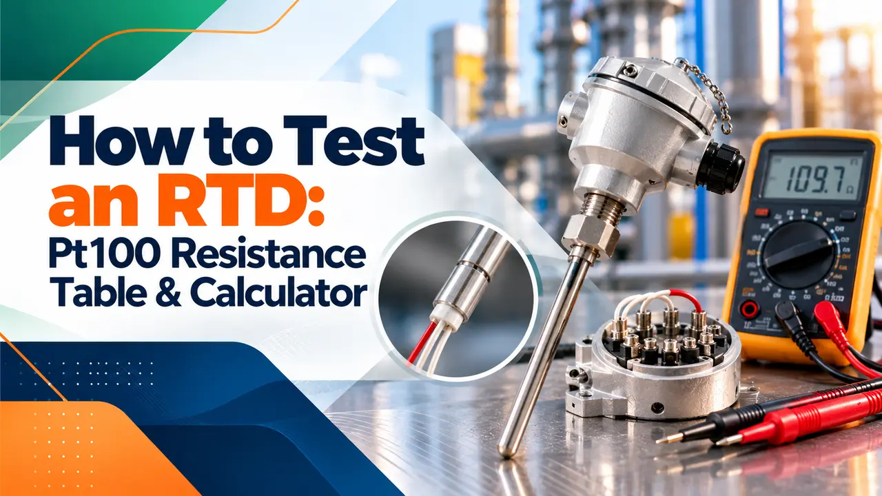
How Do You Test an RTD?
The answer to how to test an RTD is simple: isolate the sensor, measure the resistance between its different coloured wires with a multimeter and compare the value with the Pt100 table at the actual temperature. Then check that same colour wires read close to zero and that the element is well insulated from the sheath, which is how every platinum RTD is proven in the field.
- A Pt100 reads 100.00 Ω at 0 °C and 138.51 Ω at 100 °C.
- At a room temperature of 25 °C, expect about 109.7 Ω between red and white.
- Same colour wires should read close to 0 Ω, normally well below 1 Ω.
- An open circuit (OL) means a broken element or lead, a very low reading means a short.
- Insulation from element to sheath should be at least 100 MΩ.
The resistance rises by about 0.385 Ω per degree Celsius, so even a cheap multimeter can tell a good sensor from a dead one.
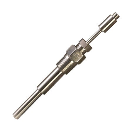
DwyerOmega explains that a Pt100 has 100 ohms at 0 °C and a Pt1000 has 1,000 ohms at 0 °C, which is the quickest way to tell the Pt100 and Pt1000 types apart. It adds that a much higher reading usually means the sensor is a thermistor, while a thermocouple shows only a very low loop resistance.
Pt100 Resistance Table for Field Testing
Use the table below to judge your reading. Values follow the IEC 60751 curve for a standard Pt100 with alpha 0.00385, so multiply by 10 for a Pt1000.
| Temperature | Pt100 resistance | Pt1000 resistance |
|---|---|---|
| minus 100 °C | 60.26 Ω | 602.6 Ω |
| minus 50 °C | 80.31 Ω | 803.1 Ω |
| 0 °C | 100.00 Ω | 1000.0 Ω |
| 20 °C | 107.79 Ω | 1077.9 Ω |
| 25 °C | 109.73 Ω | 1097.3 Ω |
| 50 °C | 119.40 Ω | 1194.0 Ω |
| 100 °C | 138.51 Ω | 1385.1 Ω |
| 150 °C | 157.33 Ω | 1573.3 Ω |
| 200 °C | 175.86 Ω | 1758.6 Ω |
| 300 °C | 212.05 Ω | 2120.5 Ω |
| 400 °C | 247.09 Ω | 2470.9 Ω |
For any value not in the table, use our RTD resistance to temperature calculator or the calculator further down this page. Remember that the table is for the element alone, so lead resistance must be removed before you compare.
Tools Needed for RTD Testing
- Digital multimeter with a 200 Ω range and good resolution
- Insulation tester (megger) set to a low test voltage
- Reference thermometer or the plant temperature indicator
- Pt100 resistance table or calculator
- Screwdriver set and terminal labels
- Permit to work and loop isolation from the control room
- Clean cloth and contact cleaner for terminals
How to Test an RTD With a Multimeter in 7 Steps
This is how to check a Pt100 with a multimeter, and the order matters because the first readings decide which later checks are needed. Each step is the same whether the sensor is wired to a temperature transmitter, a PLC card or a panel indicator.
If the readings look correct, reconnect the wires, restore the loop and watch the value settle. A good sensor that still reads wrong at the DCS usually points to transmitter configuration, such as the wrong sensor type or wire count.
Always measure at the sensor head first and then at the marshalling cabinet. If the head reading is good and the cabinet reading is not, the fault is in the cable or junction box, not the RTD.
3 Wire RTD Testing and 2 and 4 Wire Checks
The wire count changes what you expect to see, so confirm it before judging any reading. Our guide on 2, 3 and 4 wire RTDs explains why the extra leads exist.
Only two leads, so the meter reads element plus both lead resistances. Long cables add a positive error you cannot separate in the field.
One red and two white leads. White to white gives the lead loop, red to either white gives element plus one lead loop.
Two red and two white leads. Same colour pairs read near zero and any red to white pair reads the element.
The nVent Raychem RTD installation instructions give red to red readings from 0.22 to 21 Ω depending on lead length, and about 107.8 Ω red to white at 20 °C. That spread shows why a long sensor lead must be measured, not assumed.
DwyerOmega gives a neat 3 wire example: red to white read about 110 Ω and white to white read 0.6 Ω, which confirmed a healthy RTD near room temperature. A reading of 110 Ω suggests about 26 °C before lead correction, consistent with the basic RTD curve.
In a 3 wire circuit, the transmitter subtracts one lead resistance from the other. The method works only when both leads have the same length, size and terminal condition.
Resistance to Temperature Formula With Solved Example
Above 0 °C, IEC 60751 defines the Pt100 curve with the Callendar Van Dusen equation using A = 0.0039083 and B = minus 0.0000005775. Solving the quadratic for T turns any corrected reading into temperature.
Measured red to white = 110.50 Ω
White to white lead loop = 0.60 Ω
Corrected Rt = 110.50 minus 0.60 = 109.90 Ω
T = [minus A + √(A² minus 4B(1 minus Rt/R0))] ÷ 2B
T = 25.43 °C
Reference thermometer = 25.20 °C
Deviation = 0.23 °C
Class B limit at 25 °C = 0.30 + 0.005 × 25 = ±0.43 °C, PASS
The quadratic is exact above 0 °C and close enough down to minus 100 °C; colder work needs the full equation in our Pt100 calibration guide.
Insulation Resistance Test on an RTD
No method for how to test an RTD is complete without an insulation check, because a sensor with correct resistance can still drift if moisture enters the sheath. The nVent Raychem instructions call for a megohmmeter test at no more than 250 V DC, with at least 100 MΩ between the leads and the sheath.
Join all RTD wires together, connect the tester between them and the sheath or ground wire, and never apply the tester across the element itself, since that can damage it. The general method follows our megger test procedure, only at a much lower voltage.
If the insulation reading is low, warm the sensor head gently and test again. A value that recovers after drying points to moisture at the head or connector rather than inside the sheath.
RTD Fault Finding Table
Knowing how to test an RTD is only half the job; this troubleshooting table turns each reading into a likely cause. Most of these faults also show up as early warning signs on the DCS trend before the sensor fails completely.
| Reading | Likely fault | Field action |
|---|---|---|
| OL or open between red and white | Broken element or lead, loose terminal | Check at the head, then replace the insert |
| Far below the table value, near 0 Ω | Shorted element or leads | Inspect the cable for crushing, replace the insert |
| High by a fixed amount | Lead or terminal resistance, 2 wire error | Measure the lead loop, clean and tighten terminals |
| Same colour pair reads several ohms | Corroded or loose lead, wrong pairing | Re identify wires, clean terminals |
| Correct ohms, noisy reading | Moisture, low insulation, poor shield earth | Megger test, dry the head, check shield |
| Correct ohms, wrong DCS value | Wrong sensor type, wire count or range | Check transmitter setup and HART configuration |
| Reads low in process, fine on bench | Poor immersion or air gap in thermowell | Check insertion length and spring loading |
An open sensor often drives the output to its burnout value, so a sudden jump to full scale is a clue too.
A reading that is correct at ambient but wrong in the process often comes from stem conduction. If the insertion depth is too short, heat flows along the sheath and the element sits below the true fluid temperature.
How to Test an RTD Without Removing It
A smart transmitter often reports raw sensor ohms over HART, which saves a trip to the head for a first check. If you must prove accuracy at more than one point, pull the insert and use a dry block calibrator instead of guessing from ambient readings.
RTD Testing Myths
Multimeter Check vs Calibrator Test
When people ask how to test an RTD, they usually mean one of two things: is it alive, or is it accurate. A multimeter answers the first and a calibrator the second; refer to our note on temperature measurement errors when the gap is small.
- Fast, cheap and needs no process shutdown beyond isolation.
- Finds open, short and lead faults within minutes.
- Works on any 2, 3 or 4 wire sensor.
- Good first step before calling for a calibration.
- Meter resolution of 0.1 Ω equals about 0.26 °C.
- Cannot prove accuracy at temperatures other than ambient.
- Two wire readings include lead error.
- Misses intermittent faults caused by vibration or heat.
Raychem RTD Installation Instructions PDF
Video on Checking a 3 Wire RTD
How to Test an RTD FAQ
Disconnect it, measure the resistance between the different coloured wires and compare it with the Pt100 table at the actual temperature. Then confirm that same colour wires read close to zero ohms.
Finish with a low voltage insulation test from the wires to the sheath. A sensor that passes all three checks is healthy, and remaining errors usually sit in the transmitter or wiring.
A Pt100 reads about 107.8 ohms at 20 degrees and about 109.7 ohms at 25 degrees. Your meter shows a little more because lead resistance adds to the reading.
Measure the lead loop between the same colour wires and subtract it. The corrected value should sit within a few tenths of an ohm of the table figure.
Measure between the two same colour wires first, which gives the lead loop and should read well below one ohm. Then measure from the single colour wire to each of the other two.
Both of those readings should be equal and match the table plus the lead loop. A big difference between them points to a bad lead or a loose terminal on one side.
By definition, a Pt100 has exactly 100 ohms at 0 °C, and a Pt1000 has 1,000 ohms. At 100 °C, the Pt100 reaches about 138.5 ohms on the standard curve.
These two points come from IEC 60751 and give the familiar 0.00385 alpha value. Most industrial sensors used in India follow this curve, so the same table works for most brands.
Yes, but only between all wires joined together and the sheath, and at a low test voltage. The nVent Raychem instructions allow a maximum of 250 V DC and expect at least 100 megohms.
Never connect the tester across the element itself, because the voltage can damage it. Disconnect the transmitter first so that its input circuit is not stressed by the test.
The most common cause is an open element or lead, which pushes many transmitters to an upscale burnout value. A loose terminal, a broken wire or water in the head can do the same.
Measure the resistance at the head and at the cabinet to locate the break. If both read open, the insert itself has failed and needs replacement.
Related Articles
- What Is an RTD and How It Works
- RTD Sensor Connections
- Pt100 RTD Calibration Guide
- RTD Resistance to Temperature Calculator
- Thermocouple vs RTD
External References
- Raychem RTD MTO Installation Instructions, nVent
- How to Identify Temperature Probes, DwyerOmega
- Resistance Thermometer, Wikipedia
What We Learn Today
- Knowing how to test an RTD starts with the Pt100 table: 100 Ω at 0 °C, 138.51 Ω at 100 °C and about 0.385 Ω per degree.
- Same colour lead pairs should read close to zero, and the lead loop must be subtracted before you convert a reading to temperature.
- A low voltage insulation test from all wires to the sheath, at least 100 MΩ, catches the moisture faults that ohm readings miss.
