
When a large generating unit or an import line trips, grid frequency starts falling within milliseconds. Automatic relays then disconnect planned blocks of load in stages, sacrificing a few feeders so that the rest of the grid stays alive.
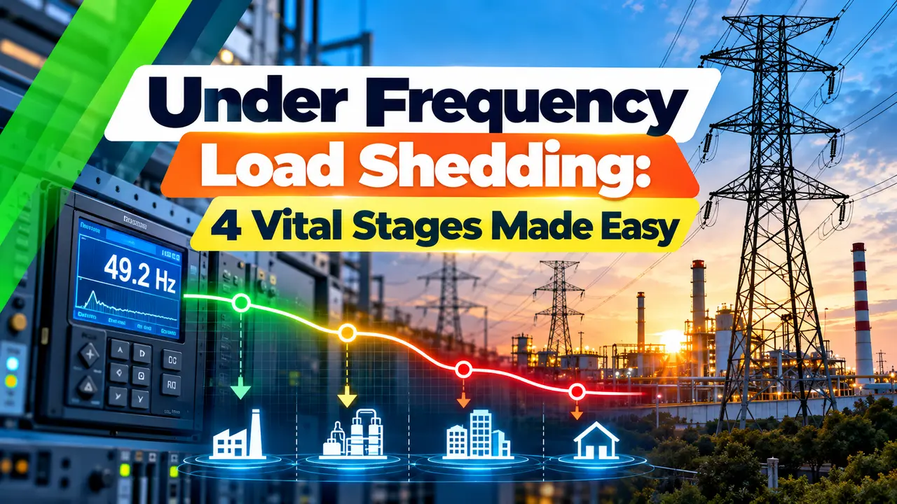
Under frequency load shedding is the last automatic defence that stops a generation shortfall from turning into a blackout. This guide explains the physics, the four Indian UFR stages, df/dt relays, islanding and how to calculate how fast frequency falls.
What Is Under Frequency Load Shedding?
Under frequency load shedding, often shortened to UFLS, is an automatic protection scheme that trips selected distribution feeders in planned steps when system frequency falls below set limits after a loss of generation. By reducing demand quickly, it restores the balance between generation and load before turbines, auxiliaries and protective relays start tripping healthy machines.
Frequency in an AC grid is a direct measure of balance. When generation exceeds load, the rotating machines speed up, and when load exceeds generation, they slow down and frequency drops.
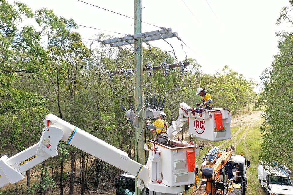
NOJA Power describes distribution reclosers and feeder breakers as a common place for automatic load shedding, since parts of the network can be dropped progressively instead of losing everything. Once generation again matches load, operators restore those feeders one by one.
Why Grid Frequency Falls After a Trip
All synchronous generators on a grid store kinetic energy in their rotors, and this stored energy, called inertia, feeds the deficit in the first seconds after a trip. The bigger the inertia, the slower the fall, which is why system studies express it as the inertia constant H on a common base, as explained in the per unit system.
Governors then raise turbine output, but they need several seconds to respond. If the frequency nadir would go below what turbines and generator excitation systems can tolerate, load must be removed first.
The SEL and Xcel Energy paper on faster load shedding notes that hydro units can ride through a frequency drop of about 10 percent, while steam turbines are sensitive to about 5 percent. Low frequency also makes blade resonance a real risk, so turbine makers specify strict time limits for each band.
Inverter based solar and wind plants have no rotating mass connected to the grid, so they add no natural inertia. NOJA Power notes this is a main reason frequency protection is becoming more common on modern networks.
India's 4 Stage UFR Settings Under IEGC 2023
Minutes of an Eastern Regional Power Committee meeting on automatic load relief, held in July 2024, quote Regulation 29(12) of the CERC Indian Electricity Grid Code 2023. It sets four default under frequency relay stages, effective from 1 October 2023.
| Stage | Frequency Setting | Share of Relief | Example Relief, ER FY 2024 25 |
|---|---|---|---|
| Stage 1 | 49.4 Hz | 5 % of peak | 1,383 MW |
| Stage 2 | 49.2 Hz | 6 % of peak | 1,660 MW |
| Stage 3 | 49.0 Hz | 7 % of peak | 1,937 MW |
| Stage 4 | 48.8 Hz | 7 % of peak | 1,937 MW |
The same minutes record that total relief is planned at 25 percent of the previous year peak demand, split by a task force as 5, 6, 7 and 7 percent. The Eastern Region proposed a revised total of 6,917 MW, with the frequency set points unchanged.
Each State Load Despatch Centre identifies feeders for every stage and the regional committees audit them. Feeder status usually reaches the control centre through an RTU and SCADA link, so the relief actually available can be checked in real time.
Never put hospitals, water supply, traction or other essential loads on a UFR feeder list. Choose mixed feeders with steady demand, because a feeder that carries little load at night gives almost no relief when it trips.
Rate of Change of Frequency Formula
For the first moments after a trip, before governors act, the swing equation gives the initial rate of fall. The SEL paper writes it for a 60 Hz system; the same relation for any nominal frequency is shown below.
Time to stage ≈ (f0 minus f stage) ÷ df/dt
ΔP = lost generation as a fraction of total, H = inertia constant in seconds
Example:
f0 = 50 Hz, ΔP = 10 % = 0.10, H = 4 s, stage = 49.4 Hz
df/dt = 50 × 0.10 ÷ (2 × 4) = 5 ÷ 8 = 0.625 Hz/s
Time to 49.4 Hz ≈ 0.6 ÷ 0.625 = 0.96 s
This linear estimate ignores load damping and governor response, so real frequency falls a little slower and the true time is longer. It is still a useful first check on whether relay delay plus breaker time is fast enough.
Frequency Decay Calculator
Second Worked Example: Sizing State Load Relief
Suppose a state had a peak demand of 20,000 MW last year. The total relief at 25 percent is 5,000 MW, split as 1,000 MW at 49.4 Hz, 1,200 MW at 49.2 Hz and 1,400 MW each at 49.0 Hz and 48.8 Hz.
For under frequency load shedding, feeder loads change with season and hour, so planners use measured feeder demand, not connected load, and add margin. The same diversity ideas used in maximum demand calculation apply when you estimate what a feeder really carries at peak.
The ERPC minutes also note an interim step in which load was shifted from stages 3 and 4 to stages 1 and 2 until new feeders were identified. Early stages that really shed their share reduce the depth of every disturbance.
Fixed Stage, df/dt and Adaptive Schemes
Each relay trips its feeder when frequency stays below a set point for a short delay.
Trip when frequency falls faster than a set rate below an enabling frequency.
Use measured disturbance size, PMU data or contingency tables to shed the right amount.
The task force recommendations recorded in the ERPC minutes describe df/dt stages enabled below 49.9 Hz, with rate settings of 0.10, 0.15 and 0.20 Hz/s. Their load quantum is tied to the largest generating station or peak import in the region, whichever is higher.
Modern numerical relays used for under frequency load shedding combine frequency, df/dt and undervoltage blocking in one device, and many substations send the trips as IEC 61850 GOOSE messages. The SEL paper reports Xcel Energy using a default delay of 6 cycles, with 30 cycles on feeders carrying significant motor load.
In the South Australia event of September 2016, the SEL paper reports frequency falling at about 6 Hz/s. That is far faster than a typical fixed stage scheme with time delays can follow.
Sequence of Events During a Generation Loss
The ERPC minutes state that energy storage systems should change from charging to discharging at 49.50 Hz, and that pumping load trips before the first stage. Removing such controllable load first spares ordinary consumers.
Islanding Schemes for Plants and Cities
If frequency keeps falling after all under frequency load shedding stages operate, islanding schemes separate a captive power plant, or a city with its own generation, from the collapsing grid. The island must hold a close match between its own generators and selected load, which needs careful load flow analysis beforehand.
Inside a process plant, a similar internal scheme sheds non essential drives so the captive generators survive a grid outage. Fast breakers matter here, and the choice between types is covered in ACB vs VCB vs SF6 circuit breaker; resynchronising later follows the normal generator synchronizing procedure.
7 Steps to Design an Under Frequency Load Shedding Scheme
- Prevents a full blackout after large trips.
- Acts within a fraction of a second, without operators.
- Sheds only as much load as the disturbance needs.
- Protects turbines from damaging low frequency.
- Feeder load varies, so actual relief is uncertain.
- Fixed stages can be too slow in low inertia periods.
- Rooftop solar on feeders can reduce net relief.
- Wrong settings can cause over shedding and overshoot.
Testing and Maintaining UFR Relays
- Inject a ramp of falling frequency and record pickup and trip time.
- Verify the undervoltage block and the df/dt enabling frequency.
- Confirm each relay trips the correct feeder breaker.
- Check that UFR status and trip events reach SCADA.
- Measure actual feeder load at peak and off peak hours.
- Remove essential loads that crept onto shedding feeders.
- Keep relay clocks synchronised for event analysis.
Correct time stamps let analysts compare relay records from many substations after an under frequency load shedding event, which is why time synchronization with NTP and PTP matters for protection teams too. After the July 2012 grid disturbances in northern and eastern India, regulators pressed strongly for regular checks on UFR and df/dt healthiness.
When a UFR operates, download the disturbance record before resetting the relay. The frequency trace, the voltage at trip and the exact time tell you whether the setting, the delay and the breaker all performed as intended.
Where Under Frequency Load Shedding Is Applied
Even on a site supplied by a DG set, a frequency dip on a large motor start can trip sensitive loads, so the generator size must suit the largest step load. Critical control systems should still sit behind a UPS.
ERPC Minutes on Automatic Load Relief
Video: How Load Shedding Protects the Grid
Under Frequency Load Shedding FAQ
It is an automatic scheme that trips planned feeder groups when grid frequency falls below set values. It restores the balance between generation and demand after a sudden loss of generation.
Relays act in several stages, so only the needed amount of load is removed. Feeders are restored by operators once enough generation is available again.
The Indian Electricity Grid Code 2023 lists four default stages at 49.4, 49.2, 49.0 and 48.8 Hz. These settings took effect from 1 October 2023.
Regional power committees then plan the load relief for each stage separately. Recent planning uses a total of about 25 percent of the previous year peak demand in each region.
The remaining generators must supply the lost power from the kinetic energy of their rotors. As they slow down, the frequency of the whole synchronous grid falls together.
Governors raise turbine output after a few seconds of delay. Until then, the rate of fall depends mainly on the size of the loss and the system inertia.
It measures how fast frequency is changing rather than only its value. It can therefore trip load earlier when a very large loss causes a steep fall.
Indian task force settings discussed by ERPC use rates such as 0.10, 0.15 and 0.20 Hz/s. These elements are enabled only when frequency is already below 49.9 Hz.
It must act before frequency reaches limits that trip turbines or auxiliaries. Typical schemes use short relay delays of a few cycles plus breaker time.
Our calculator shows a 10 percent loss with H of 4 seconds reaching 49.4 Hz in about one second. Slow breakers or long delays can therefore let the frequency fall too far.
Hospitals, water supply, defence, traction and other essential services should stay off shedding feeders. Their sudden loss can create safety risks far worse than a short planned power cut.
Planners instead choose mixed residential and commercial feeders with fairly steady demand. They also review the list each season as new essential connections appear on the network.
Yes, because a feeder with heavy solar export may carry little or even reverse power at midday. Tripping it then removes generation as well as load, and the net relief becomes small.
Planners therefore measure net feeder flow at different hours. Some utilities move such feeders to later stages or exclude them from the list.
Related Articles
- Protective Relays Explained
- Generator Excitation System and AVR
- Generator Synchronizing Procedure
- Per Unit System in Power System
- Load Flow Analysis for Industrial Plants
External References
- Minutes of Meeting on AUFLS, Eastern Regional Power Committee
- Frequency Protection Explained: Variants and Rationale, NOJA Power
- Utility Frequency, Wikipedia
What We Learn Today
- Under frequency load shedding trips planned feeder blocks in stages when frequency falls after a generation loss, so the remaining grid avoids a blackout.
- India uses four default UFR stages at 49.4, 49.2, 49.0 and 48.8 Hz under IEGC 2023, planned at about 25 percent of previous year peak.
- The initial rate of fall equals f0 times the lost power fraction divided by twice the inertia constant, so low inertia grids need faster df/dt protection.