
Every factory has one main LT board where transformer and generator power first meets the plant loads. That power control centre decides how safely and reliably every motor, light and computer downstream will run.
A PCC panel is the main low voltage switchboard that receives power from transformers and DG sets and distributes it to MCCs and distribution boards. This guide explains its parts, interlocks, ratings and selection for Indian plants.
What Is a PCC Panel?
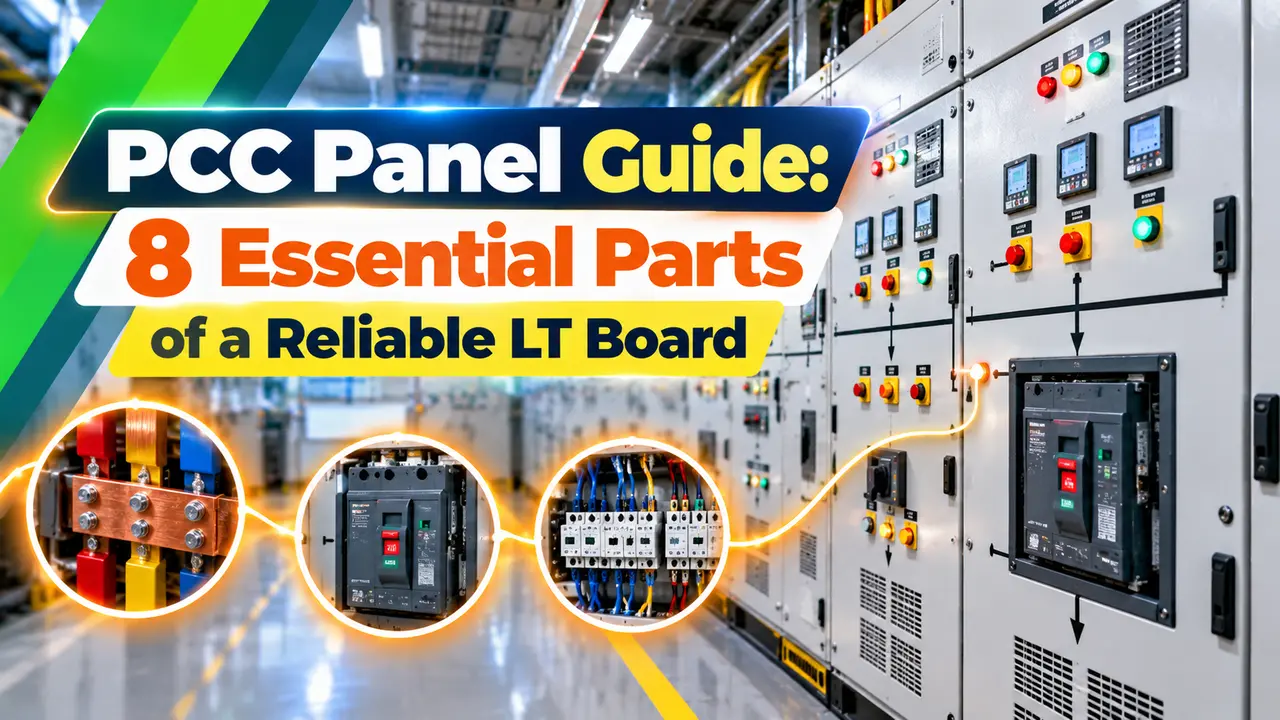
A PCC panel, or power control centre, is the main low voltage switchboard of a plant that receives power from one or more transformers or generators and distributes it to motor control centres, distribution boards and large single loads. It sits at the top of the LT system, just downstream of the transformer, and carries the full plant current on its main busbars.
Edvard Csanyi of Electrical Engineering Portal describes main distribution boards, also called power centres, as assemblies placed directly downstream of MV/LV transformers or generators. In Indian practice this same board is called the PCC, and it usually works at 415 V or 433 V, 50 Hz.
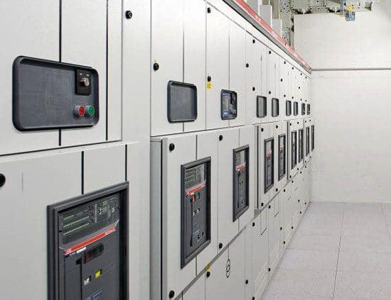
A PCC panel is built as a row of floor standing cubicles, with incomer sections, a bus coupler and many outgoing feeder modules. It is the starting point of the power distribution system for the whole site.
PCC Panel vs MCC: Clear Differences
| Point | PCC Panel | MCC |
|---|---|---|
| Main job | Receive and distribute bulk power | Start, stop and protect motors |
| Fed from | Transformer LV or DG set | PCC outgoing feeder |
| Incomer device | ACB, often 800 A to 4000 A | MCCB or ACB |
| Outgoing feeders | MCCBs or ACBs to MCCs and DBs | MPCB or MCCB with contactor and overload relay |
| Typical loads | MCCs, PDBs, APFC, big chillers | Pumps, fans, compressors, conveyors |
| Control logic | Changeover, interlocks, load shedding | Local and remote motor control |
In short, the PCC panel handles power while the motor control centre handles motors. Many small plants combine both in one board called a PMCC, with power feeders and motor starters sharing the same busbar.
Electrical Engineering Portal notes that IEC 61439 1 requires switchboards in normal environments to be enclosed, giving at least IPXXB protection against direct contact. Open switchboards with accessible live parts are only allowed inside closed electrical operating areas.
8 Essential Parts of a PCC Panel
| Part | Function | Typical Device |
|---|---|---|
| Incomer | Brings power from transformer or DG | ACB with microprocessor release |
| Bus coupler | Joins or splits two bus sections | ACB with interlocks |
| Main busbars | Carry the full current along the board | Copper or aluminium bars on insulators |
| Outgoing feeders | Feed MCCs, DBs and large loads | MCCB or ACB |
| Metering | Shows V, A, kW, kWh, PF | Multifunction meter with CTs |
| Protection relays | Earth fault, under voltage, reverse power | Numerical relays, ELR with CBCT |
| Control and interlock wiring | Changeover logic and permissives | Relays, PLC, key interlocks |
| Enclosure and separation | Protects people and limits arcs | Form 2b to Form 4b cubicles |
The incomer ACB has a release with long time, short time, instantaneous and earth fault elements. Choosing between air, vacuum and SF6 breakers is explained in ACB vs VCB vs SF6 circuit breaker, and LT boards almost always use ACBs.
Metering uses current transformers with 5 A or 1 A secondaries feeding a multifunction meter or a power analyser. The same CT cores can feed protection relays when the accuracy class suits both duties.
Ask the panel builder for a separate metering CT and protection CT on the incomer. A metering class core can saturate during a fault and starve the relay of signal.
How Power Flows Through a PCC Panel
The link from the transformer to the incomer is often a bus duct rather than many parallel cables, because it is compact and easier to terminate at high currents. A DG set connects to a separate incomer or to the same bus through a changeover arrangement.
Bus Coupler and Interlock Logic
A typical Indian PCC panel has two transformer incomers I1 and I2 and one bus coupler BC. The common rule is that only two of these three breakers may be closed at any time, so the two transformers never run in parallel on the LT side unless the design allows it.
I1 and I2 closed, BC open, each transformer feeds its own section.
I1 open, BC and I2 closed, one transformer feeds both sections.
Mains incomers open, DG incomer closed on essential bus.
Interlocks are provided both electrically, through auxiliary contacts in the closing circuits, and mechanically, through key or cable interlocks. Automatic changeover between mains and DG works like an automatic transfer switch, built from ACBs and a controller.
Paralleling two transformers on the LT bus roughly doubles the available fault current at the board. That is a main reason why the two out of three interlock is so common in Indian substations.
Forms of Separation in a PCC Panel
IEC 61439 2 defines forms of internal separation that decide how busbars, functional units and cable terminals are divided by barriers. The BEAMA guide explains that Form 1 has no internal separation, while Form 4 separates busbars, every functional unit and their terminals from each other.
| Form | Busbars vs Units | Units vs Units | Terminals vs Busbars | Terminals vs Terminals |
|---|---|---|---|---|
| Form 1 | No | No | No | No |
| Form 2a | Yes | No | No | No |
| Form 2b | Yes | No | Yes | No |
| Form 3a | Yes | Yes | No | No |
| Form 3b | Yes | Yes | Yes | No |
| Form 4a | Yes | Yes | Yes | Yes, same compartment as unit |
| Form 4b | Yes | Yes | Yes | Yes, separate compartment |
A critical process plant usually specifies Form 3b or Form 4b for its PCC panel, so that one feeder can be worked on while the rest stay live. Such work still needs a proper isolation and permit to work procedure.
Write the required form and its type number into the specification, for example Form 4b Type 6. A plain Form 4 request lets builders choose the cheapest version.
Sizing the Incomer and Fault Level
The incomer rating starts from the transformer full load current, and the busbar short time rating starts from the prospective fault current. A full method for the transformer side is shown in transformer kVA rating calculation.
Prospective fault current Isc ≈ I × 100 ÷ Z percent
Example: 1600 kVA, 433 V, Z = 6.25 percent (from nameplate)
I = 1600 × 1000 ÷ (1.732 × 433) = 2133.4 A
Next standard ACB frame = 2500 A
Isc = 2133.4 × 100 ÷ 6.25 = 34.1 kA
This simple fault current assumes an infinite upstream source, so it gives a safe upper value for the board. A detailed method that includes cable and source impedance is given in short circuit fault current calculation.
PCC Panel Incomer Calculator
Second Worked Example: A 1000 kVA Plant
A smaller plant has a 1000 kVA, 433 V transformer with 5 percent impedance on its nameplate. The full load current is 1000 × 1000 ÷ (1.732 × 433) = 1333.4 A, so a 1600 A ACB frame fits.
The prospective fault current is 1333.4 × 100 ÷ 5 = 26.7 kA. The busbars and every outgoing breaker in this PCC panel therefore need a short circuit rating of at least that value, with some margin for future growth.
Protection and Metering Schemes
Settings on the incomer must grade with the outgoing feeder breakers so that only the faulty feeder trips. The method is explained in breaker coordination and selectivity.
Most plants also keep a capacitor bank feeder in the PCC panel to hold the power factor near unity, as described in APFC panel working and sizing. Many Indian utilities levy charges for poor power factor, so this feeder often pays for itself.
- Single point to switch and protect plant power.
- Bus coupler gives flexibility during outages.
- Forms 3b and 4b allow safer feeder maintenance.
- Central metering supports energy audits.
- Clear interlocks prevent wrong paralleling.
- High fault level demands costly breakers.
- Large footprint and heavy cable entries.
- A busbar fault can stop the whole plant.
- Higher forms of separation raise cost and size.
- Needs trained staff and strict permits.
Commissioning Checklist for a New PCC Panel
- Verify the design verification certificates to IEC 61439.
- Torque check all busbar and cable joints.
- Measure insulation resistance of busbars and feeders.
- Test incomer and bus coupler interlocks in every mode.
- Inject secondary current into ACB releases and relays.
- Check CT polarity, ratio and meter readings.
- Confirm earthing of the frame and neutral links.
- Take an infrared scan after one week on load.
An infrared scan after loading picks up loose joints before they burn, as shown in infrared thermography of electrical panels. Repeat the scan every year as part of preventive maintenance.
PCC Panel Selection Points for Indian Plants
Specify the rated current, rated short time current Icw for 1 second, form of separation, IP rating, busbar material and incomer arrangement. Ask for design verification to IS/IEC 61439, which replaced the older type tested and partially type tested concept.
Leave enough spare feeders and busbar capacity in the PCC panel for future expansion of the plant. Plan cable entry, ventilation and the room layout early, because a power control centre is hard to modify once installed.
BEAMA Guide to Forms of Separation
Power Control Centre Explained on Video
PCC Panel FAQ
It is the main low voltage switchboard that receives power from transformers or DG sets. It then distributes that power to MCCs, distribution boards and large single loads across the plant.
It usually has ACB incomers, a bus coupler and many outgoing feeders on a common busbar. The board sits at the top of the LT system in most Indian factories and buildings.
A PCC distributes bulk power from the transformer to many downstream boards. An MCC starts, stops and protects individual motors using starters, contactors and overload relays.
The PCC panel usually feeds each MCC through its own outgoing breaker. Small plants often combine both functions in a single PMCC board that shares one common busbar system.
A bus coupler joins or separates two busbar sections that are fed by different incomers. It lets one transformer feed both sections when the other one is under maintenance.
Interlocks usually allow only two of the three breakers to close together at any time. This prevents unplanned paralleling of transformers and the higher fault level it would cause.
Form 3b or Form 4b suits critical plants where feeders must be worked on while the board stays live. Form 2b is cheaper and often fine for smaller commercial buildings.
Always state the form and its type number clearly in the specification. Cost, size and heat dissipation all rise as the level of internal separation goes higher.
Calculate the transformer full load current from kVA, voltage and the square root of three. Then select the next standard ACB frame above that current value.
For example, a 1600 kVA, 433 V transformer gives about 2133 amperes. A 2500 A frame suits it, provided its breaking capacity also exceeds the calculated fault level of the board.
IS/IEC 61439 1 and 61439 2 cover low voltage switchgear and controlgear assemblies in India. They define design verification, temperature rise limits and short circuit withstand.
The forms of separation are defined in part 2 of the standard. Breakers inside follow IEC 60947 2, while the installation itself follows IS 732 and the local rules.
Check joint tightness, clean dust and verify insulation resistance during every planned shutdown. Test the interlocks and the ACB releases with secondary injection at regular intervals.
An annual infrared scan finds hot joints while the board is still on load. Keep the switchroom dry, well ventilated and free of any stored material at all times.
Related Articles
- Motor Control Center MCC Explained
- ACB vs VCB vs SF6 Circuit Breaker
- Busbar Sizing Calculation Guide
- Bus Duct and Busway System
- Automatic Transfer Switch ATS Explained
External References
- Guide to Forms of Separation, BS EN 61439 2, BEAMA
- Forms of Separation in LV Switchboards, Electrical Engineering Portal
- Switchgear, Wikipedia
What We Learn Today
- A PCC panel is the main LT board that takes power from transformers or DG sets through ACB incomers and feeds MCCs, DBs and large loads.
- Two incomers with a bus coupler usually follow a two out of three interlock, so the transformers never run in parallel unless designed for it.
- Size the incomer from full load current, check the fault level with transformer impedance and specify the form of separation with its type number.