
A large actuator can take many seconds to fill when only the positioner supplies the air, which is too slow for surge, trip and pressure control duties. A volume booster copies the positioner signal and adds plenty of air flow, so the valve strokes fast yet still positions accurately.
Large control valves often move too slowly because the positioner relay cannot pass enough air. A correctly installed and tuned volume booster solves that problem without making the loop unstable.
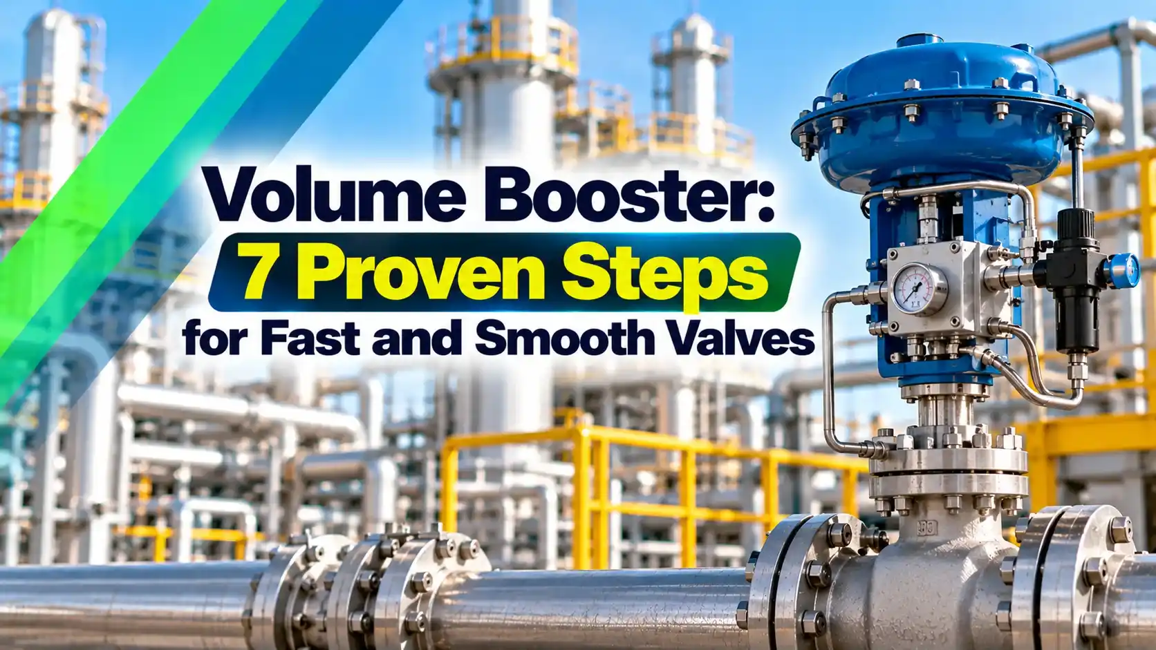
What Is a Volume Booster?
A volume booster is a pneumatic relay with a fixed 1:1 ratio that takes the small output signal of a valve positioner and reproduces the same pressure at the actuator, while drawing a much larger air flow straight from the supply line. It sits between the valve positioner and the actuator and makes big valves stroke many times faster.
A positioner relay has small internal passages, so it is designed for accuracy, not for flow. On a large diaphragm or piston actuator with tens of litres of volume, that small flow means stroking times of 20 seconds or more.

The volume booster does not change the control signal, it only adds air capacity. The positioner still decides the final valve position, and the booster just helps the actuator get there quickly.
Inside the Booster: How the Relay Works
Inside the body there are two diaphragms, a supply valve and an exhaust valve held on a common stem. The signal pressure from the positioner acts on the top diaphragm and the output pressure acts on the bottom one.
When the signal is higher than the output, the force imbalance opens the supply port, and air rushes into the actuator. When the signal falls, the exhaust port opens and dumps actuator air to atmosphere through a large vent.
Most boosters have a small deliberate deadband, so tiny signal changes do not open the main ports at all. Emerson states a nominal deadband of 2 to 5 percent of positioner output span for the Fisher 2625, depending on the exhaust port size.
The Bypass Needle Valve and Why It Matters
Every good volume booster has an adjustable bypass restriction, usually a needle screw, between the signal port and the output port. It works like a small needle valve that lets the positioner feed the actuator directly for small changes.
For small steps, the positioner air passes through the bypass and the booster ports stay closed, so positioning stays smooth and precise. For large steps, the pressure difference across the bypass grows until the volume booster opens fully and delivers its high flow.
If the bypass is closed too far, even small changes force the booster to act, and the valve overshoots and hunts. If it is open too far, the pressure difference never builds up and the booster hardly helps.
Start with the needle about four turns open from fully closed, as the Fisher 2625 manual suggests, then close it gradually during step tests. Stop when large steps are fast and small steps still settle without overshoot.
7 Steps to Install and Tune a Volume Booster
Use the same regulator for the positioner and the volume booster, because a different supply pressure upsets the balance and can lock the valve in one position. Clean and dry air is essential, as explained in water vapour in instrument air lines.
Moisture and oil that freeze or stick inside a booster cause sluggish or erratic movement. Keep the instrument air dew point well below the lowest ambient temperature at site.
Stroking Time and Air Volume Formula
A quick estimate of stroking time compares the free air needed to fill the actuator with the flow the pneumatic path can deliver. Free air is the actuator volume multiplied by the absolute pressure ratio.
Fill time: t = Vfree ÷ Q × 60
V in litres, P in bar gauge, Q in normal litres per minute, t in seconds
Example:
V = 20 L, P = 4 bar g
Vfree = 20 × 5.013 ÷ 1.013 = 98.97 L
With booster, Q = 1500 Nl/min: t = 98.97 ÷ 1500 × 60 = 3.96 s
Without booster, Q = 150 Nl/min: t = 39.59 s
This is a rough average flow method, because real flow falls as the actuator pressure approaches supply pressure. Treat the result as a guide for selection, and confirm the actual time in a stroke test.
Actuator Fill Time Calculator
Second Worked Example: Anti Surge Valve
An anti surge controller may need its recycle valve to open in about 2 seconds. Suppose the piston actuator has 30 L of volume and works at 5 bar g.
Free air is 30 × 6.013 ÷ 1.013 = 178.07 L, so a 2 second stroke needs an average of 178.07 ÷ 2 × 60 = 5342 Nl/min. One booster may not be enough, so engineers often fit two boosters in parallel or choose a larger model.
ControlAir lists its Type 6000 booster at 300 scfm, about 7075 Nl/min, with a forward Cv of 6.6 on the 1/2 inch version. A unit of that class could meet this duty if the supply tubing and regulator are sized to match.
Fixing Instability After Adding a Volume Booster
The most common complaint after fitting a volume booster is a valve that hunts or overshoots around setpoint. The positioner loop now drives a much faster actuator, so its tuning and the bypass must be matched to the new speed.
| Symptom | Likely Cause | Fix |
|---|---|---|
| Valve hunts on small steps | Bypass closed too far | Open the needle a little |
| Large steps still slow | Bypass open too far or small supply | Close the needle, upsize tubing |
| Overshoot on big steps | Positioner gain too high | Lower gain or run autotune again |
| Output drifts or creeps | Supply leak or wrong common supply | Check tubing and regulator |
| Booster chatters | Undersized supply or blocked filter | Clean filter, raise regulator capacity |
| Valve sticks at one end | Separate supply pressures | Use one common regulator |
Always run the positioner autotune again after a booster is installed, because the actuator now responds faster. Problems that remain often come from friction or packing, covered in control valve troubleshooting.
Fit a pressure gauge on the booster output during commissioning. If the output follows the signal smoothly on small steps, the bypass and positioner are in harmony.
Fail Action, Trip Duty and Safety Valves
A volume booster does not change the fail safe position of the valve on air failure. When supply is lost, the actuator spring drives the valve to its fail position and the actuator air vents through the booster exhaust.
On trip valves, the booster is often combined with a solenoid valve or a quick exhaust valve so the actuator vents within the required time. Such valves are part of the emergency shutdown system, and Emerson offers the Fisher 2625 in a version with an SIS safety manual.
A quick exhaust valve and a volume booster are not the same thing. A quick exhaust only dumps air fast on venting, while a booster both fills and exhausts in proportion to the signal.
For safety valves that use a volume booster, include it in proof tests and partial stroke testing. A booster that sticks can slow venting and stretch the safety response time.
Selecting a Pneumatic Booster
General purpose 1:1 relay with adjustable bypass.
Same function with 316 body and trim.
Larger ports and higher Cv for big actuators.
- Required stroking time in both directions
- Actuator type, volume and maximum pressure
- Supply pressure and regulator capacity
- Port sizes and supply tubing diameter
- Cv of supply and exhaust ports
- Deadband and bypass adjustment type
- Body material for the site environment
- Hazardous area and SIL documentation needs
Check the actuator pressure rating first, because some diaphragm actuators are limited to about 2.8 bar while piston actuators often work up to 10 bar. The wider topic of valve actuator types and applications helps match booster and actuator.
Size the supply tubing and regulator so that their capacity exceeds the booster demand, otherwise the booster just moves the bottleneck upstream. For rotary valves, also consider the scotch yoke or rack and pinion actuator volume on both sides of the piston.
- Cuts stroking time on large actuators.
- Keeps positioner accuracy for small steps.
- Simple, no electrical power needed.
- Works with single or double acting actuators.
- Needs careful bypass tuning.
- Adds air consumption and possible leak points.
- Can cause hunting if wrongly set.
- Needs a large, clean air supply.
Common Volume Booster Installation Mistakes
Using a small regulator or 1/4 inch tubing for supply is the classic mistake, and it wastes the booster capacity. Emerson asks for at least 1/2 NPT piping for the 2625 and a high capacity filter upstream.
Another mistake is mounting the volume booster far from the actuator with long thin tubing, which adds volume and delay. Mount it close to the actuator inlet, as shown in typical control valve assemblies.
Volume Booster Data Sheet and Manual
The Emerson manual below gives the installation and bypass adjustment steps for the Fisher 2625 series. Read it together with the control valve sizing requirements so actuator and air supply are chosen together.
Pneumatic Booster Demonstration Video
Volume Booster FAQ
It reproduces the positioner output pressure at a 1:1 ratio while supplying much more air flow from the supply line. The actuator therefore fills and exhausts far faster than it would with the positioner relay alone.
The positioner still controls the final position of the valve through its feedback linkage. The booster only adds air capacity and leaves the control signal itself completely unchanged.
The bypass lets small signal changes pass directly from the positioner to the actuator without opening the main booster ports. This keeps small movements smooth and avoids overshoot around the setpoint.
For large changes the pressure difference across the needle grows and the booster opens fully. Adjusting the needle therefore sets the point where the booster starts to help the positioner.
First open the bypass needle a little, since a closed bypass makes the booster react to tiny changes. Then run the positioner autotune again so it learns the faster actuator response.
Also check that the positioner and booster share one common regulated supply. Undersized supply tubing, a choked filter and small leaks can also cause unstable movement.
No, the fail position is still set by the actuator spring and its air to open or air to close arrangement. On air loss the spring drives the valve to its fail position as before.
The actuator air simply vents through the booster exhaust port during that movement. On trip valves, a solenoid valve or quick exhaust is often added for very fast venting.
Calculate the free air needed as the actuator volume multiplied by the absolute pressure ratio. Divide that free air by the required stroking time to get the average flow in normal litres per minute.
For 30 litres at 5 bar gauge in 2 seconds, about 5342 normal litres per minute is needed. Compare that figure with the booster rating and with the supply and regulator capacity.
Yes, very large actuators sometimes use two boosters in parallel to reach short stroking times. Both must receive the same positioner signal and be fed from a large common supply.
Tune each bypass needle in the same way so the two units share the load evenly. Test small and large steps after commissioning to confirm stable and repeatable behaviour.
Clean and dry instrument air is the most important need for a long service life. Check the filter regulator, drain moisture and listen for leaks during routine field rounds.
Replace diaphragms and soft seats when the unit starts to leak or respond slowly. Always verify stroking time with a step test after any repair or replacement.
Related Articles
- Control Valve Positioner Working
- Diaphragm Actuator vs Piston Actuator
- Fail Safe Valve Positions Explained
- Control Valve Troubleshooting
- Compressor Anti Surge Controller
External References
- Fisher 2625 Volume Booster Instruction Manual, Emerson
- Type 6000 High Flow Capacity Volume Booster, ControlAir
- Control Valve, Wikipedia
What We Learn Today
- A volume booster is a 1:1 pneumatic relay that copies the positioner signal and adds large air flow so big actuators stroke many times faster.
- The bypass needle lets small changes pass directly to the actuator, while large steps open the relay fully, giving speed without hunting or overshoot.
- Fill time is roughly free air divided by flow, so 20 litres at 4 bar gauge fills in about 4 seconds at 1500 normal litres per minute.