
A digital pressure gauge replaces the Bourdon tube, gears and pointer with a silicon sensor, a converter and a clear numeric display. Used correctly, it becomes a dependable field instrument and a portable reference for checking other gauges.
Electronic gauges read pressure as numbers, not pointer angles, so parallax and pointer friction disappear. This guide explains how a digital pressure gauge works, how to read its accuracy and how to use it as a reference.

What Is a Digital Pressure Gauge?
A digital pressure gauge is a self contained instrument that senses process pressure with an electronic sensor and shows the value as numbers on an LCD or LED display. It does the same job as a mechanical Bourdon tube pressure gauge, but without any moving parts in the measuring path.
Inside the case sit a pressure sensor, an amplifier, an analog to digital converter, a microcontroller and a display. Most models use the silicon sensing element explained in piezoresistive vs capacitive pressure sensors, because it is robust, small and lower in cost.
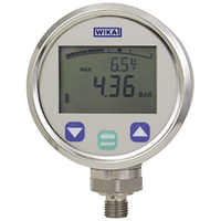
Engineers in Indian plants meet these gauges in three roles: as permanent process indicators, as portable test gauges for calibration, and as data loggers for pressure tests. The basic choice between electronic and mechanical sensing is discussed in electronic vs mechanical pressure sensors.
How the Gauge Turns Pressure Into Numbers
The process pressure acts on a thin diaphragm, usually stainless steel in front of a silicon chip, with silicone oil carrying the pressure between them. The silicon chip has four resistors diffused into it, connected as a bridge.
When the diaphragm bends, two resistors are stretched and two are compressed, so their resistance changes in opposite directions. The bridge, the same circuit described in Wheatstone bridge applications, converts this tiny change into a millivolt output proportional to pressure.
An amplifier raises the millivolt signal, and an analog to digital converter turns it into a number, as explained in analog to digital conversion. The microcontroller then applies stored correction tables for non linearity and temperature, which is why a good electronic gauge holds its accuracy across a wide ambient range.
Silicon piezoresistors change resistance far more strongly with strain than metal foil gauges do. That higher sensitivity is why a tiny silicon chip can resolve pressure changes of a few parts in ten thousand.
Accuracy, Resolution and Range Explained
Accuracy of a digital pressure gauge is normally stated as a percentage of full scale, written % FS. A 0 to 25 bar gauge with 0.05 % FS accuracy may be wrong by plus or minus 0.0125 bar anywhere in its range, the same idea as the classes in pressure gauge accuracy classes.
Some premium gauges quote accuracy as a percentage of reading, or as a combination of reading and full scale. Ralston Instruments points out that two gauges can only be compared fairly when their accuracy is stated the same way and their ranges match.
Resolution is the smallest digit the display shows, and it is not the same as accuracy. ICS Schneider Messtechnik notes that a gauge showing 10.000 bar may still carry a permissible deviation of plus or minus 0.050 bar, a point covered well in accuracy vs precision.
WIKA specifies its CPG500 basic digital pressure gauge at 0.25 % FS plus or minus 1 digit, with a measuring rate of 10 ms, which means 100 readings per second. Its eight ranges run from minus 1 to 16 bar up to 0 to 1000 bar, and two AA cells last about 1500 hours.
Always choose the smallest range that still covers your maximum test pressure. A percentage of full scale error becomes a large absolute error when a 250 bar gauge is used to check a 10 bar instrument.
Reference Error and Test Accuracy Ratio Formula
When a digital pressure gauge serves as a reference, its absolute error must be much smaller than the tolerance of the device under test. ICS Schneider recommends a test accuracy ratio of at least 4 : 1, the same principle discussed in measurement uncertainty in calibration.
Device tolerance = Device span × Class % ÷ 100
TAR = Device tolerance ÷ Reference error
Example:
Reference gauge 0 to 25 bar, 0.05 % FS
Reference error = 25 × 0.05 ÷ 100 = 0.0125 bar
Device under test 0 to 10 bar, class 1.0
Device tolerance = 10 × 1.0 ÷ 100 = 0.100 bar
TAR = 0.100 ÷ 0.0125 = 8.0 : 1, acceptable
The ratio of 8 : 1 comfortably beats the 4 : 1 minimum, so the reference contributes little to the result. If the ratio falls below 4 : 1, pick a better reference or a smaller range before you sign any certificate.
Test Accuracy Ratio Calculator
Second Worked Example: Wrong Range Choice
Suppose the same 0.05 % FS accuracy is bought in a 0 to 250 bar range and used to check the same 10 bar class 1.0 gauge. The reference error becomes 250 × 0.05 ÷ 100 = 0.125 bar, which is larger than the 0.100 bar tolerance being tested.
The ratio is now 0.100 ÷ 0.125 = 0.8 : 1, so the check is meaningless even though the reference has a fine percentage figure. ICS Schneider uses exactly this comparison to show that range selection matters as much as the accuracy class.
Power Options and Output Types
Runs on AA, AAA or coin cells with auto power off to stretch life.
Draws power from a 4 to 20 mA loop and shows the local value.
24 V DC supply with analog output or switch contacts.
Stores readings with time stamps for later download.
Battery models suit test benches and remote points where no power is wired, and Tameson notes they keep reading during a power outage. Loop powered versions sit inside a 4 to 20 mA current loop and take their energy from the loop current itself.
Gauges with outputs blur the line between gauge and transmitter, so it helps to understand the difference covered in pressure gauge vs pressure transmitter. For hazardous areas, check the Ex marking and the battery type allowed by the certificate, as explained in explosion proof vs intrinsically safe instruments.
A logging digital pressure gauge can replace a paper chart recorder during a pipeline hydro test. The stored file shows every reading with its time, which makes the test record far easier to review and archive.
Digital Versus Analog Gauge in the Field
| Feature | Digital Gauge | Analog Bourdon Gauge |
|---|---|---|
| Sensing | Silicon or thin film sensor | Bourdon tube, linkage, pointer |
| Typical accuracy | 0.025 to 0.5 % FS | 0.5 to 2.5 % of span |
| Reading | Numeric, no parallax | Pointer on dial, parallax possible |
| Power | Battery, loop or supply | None needed |
| Extra features | Min and max, tare, logging, units | None |
| Pulsation | Damping filter in firmware | Needs liquid fill or snubber |
Ralston Instruments notes that the Bourdon tube design dates from 1849 and has served for over 170 years. Mechanical gauges still win where no power is acceptable and only an occasional glance is needed, while the digital type wins wherever accuracy, recording and unit flexibility matter, as weighed in pressure gauge selection factors.
6 Smart Steps to Use a Digital Pressure Gauge as a Test Gauge
The five point rising and falling sequence matches the procedure described by ICS Schneider and catches both error and hysteresis. A dead weight tester or a multifunction process calibrator can generate the pressure, while the gauge acts as the reading standard.
Zero a gauge pressure model only when it is open to atmosphere, never while connected to a live line. A false zero adds a fixed offset to every point you record afterwards.
Selection Checklist for Indian Plants
- Range about 1.5 to 2 times the normal working pressure
- Accuracy class and whether it is % FS or % of reading
- Gauge, absolute or compound reference
- Wetted material suited to the process medium
- Process connection, often half inch NPT or G half inch
- IP rating for outdoor monsoon conditions
- Battery life, loop power or external supply
- Ex certification for hazardous zones
- Logging, units and peak hold features needed
Ask the supplier whether readings are gauge or absolute, since the difference explained in absolute vs gauge pressure is a common source of 1 bar errors. Also confirm the overload rating, and add protection as described in pressure gauge over range protection where spikes are likely.
- No parallax and easy numeric reading
- Higher accuracy than most mechanical gauges
- Peak hold, tare, unit switching and logging
- No pointer flutter thanks to digital damping
- Ideal portable reference for calibration
- Needs batteries or an external supply
- Higher purchase cost than a dial gauge
- Display can be hard to read in direct sunlight
- Hazardous areas need certified versions
- Electronics can be damaged by severe surges
Installation and Troubleshooting Tips
Mount the gauge so the display faces the operator and the sensor is not exposed to radiant heat. On steam lines use a siphon, and on pump discharge add a pressure snubber so spikes do not overload the diaphragm.
A reading that creeps upward in sunlight usually points to a temperature effect rather than real pressure, the same issue seen in pressure transmitter temperature effects. Water hammer can also cause a permanent zero shift, as discussed in hammer effect in pressure gauges.
WIKA CPG500 Digital Pressure Gauge Data Sheet
Digital Test Gauge Overview Video
Digital Pressure Gauge FAQ
Pressure bends a diaphragm that strains piezoresistors arranged in a bridge on a silicon chip. The bridge then produces a small millivolt signal that changes in direct proportion to the applied pressure.
An amplifier and converter turn that voltage into a number. The processor corrects it for temperature and non linearity and shows it on the display.
It means the error can be up to 0.05 percent of the full scale value at any point in the range. On a 25 bar gauge that is plus or minus 0.0125 bar.
The same error applies at low readings, so the percentage of reading gets worse near zero. Choose the smallest suitable range to keep that error small.
No, resolution is only the smallest step the display can show. A gauge can show three decimal places and still be wrong in the second decimal.
Accuracy comes from the sensor, the electronics and the quality of the last calibration. Always read the accuracy statement on the data sheet rather than counting digits on the display.
A common rule is that the reference should be at least four times more accurate than the device under test. ICS Schneider recommends this 4 : 1 minimum for gauge checks.
Higher ratios such as 10 : 1 are even better when available. Below 4 : 1, the reference error becomes a large part of the result.
Battery life depends on the model, the display backlight setting and the chosen measuring rate. WIKA states about 1500 hours from two AA cells for its CPG500.
Auto power off and a lower update rate stretch the life further. Carry spare cells of the type approved in the certificate when working in classified hazardous areas.
A gauge with a 4 to 20 mA output can send a signal to a controller in simple cases. It still lacks many transmitter features such as HART diagnostics and remote configuration.
For control and safety loops a proper transmitter is the better choice. A gauge is best used for local indication, logging and testing.
Most plants calibrate reference gauges every 12 months and process gauges according to their criticality. Overpressure, drops or unusual readings call for an earlier check.
Keep the certificate with the gauge and always record both the as found and the as left results. Trends from past certificates help you set the right interval for each instrument.
Related Articles
- Piezoresistive vs Capacitive Pressure Sensor
- Pressure Gauge Accuracy Classes
- Dead Weight Pressure Tester
- Bourdon Tube Pressure Gauges
- Pressure Gauge Selection Factors
External References
- Digital Pressure Gauge Model CPG500 Data Sheet, WIKA
- Digital Pressure Gauge as a Reference, ICS Schneider Messtechnik
- Pressure Measurement, Wikipedia
What We Learn Today
- A digital pressure gauge uses a piezoresistive bridge, an amplifier, a converter and a processor to show pressure as clear numbers without moving parts.
- Accuracy stated as % FS gives the same absolute error across the range, so choosing the smallest suitable range keeps readings truly accurate.
- When used as a reference, the gauge should give a test accuracy ratio of at least 4 : 1 against the tolerance of the device under test.