
Moving thousands of megawatts across a subcontinent with AC means huge corridors, reactive power problems and stability limits. Direct current links solve these problems by carrying bulk power point to point with lower losses, fewer towers and full control of the flow.
India now runs some of the longest ±800 kV HVDC transmission links in the world, carrying power from central coal and renewable hubs to distant load centres. This guide explains how converters work, when DC beats AC and how the main link types differ.
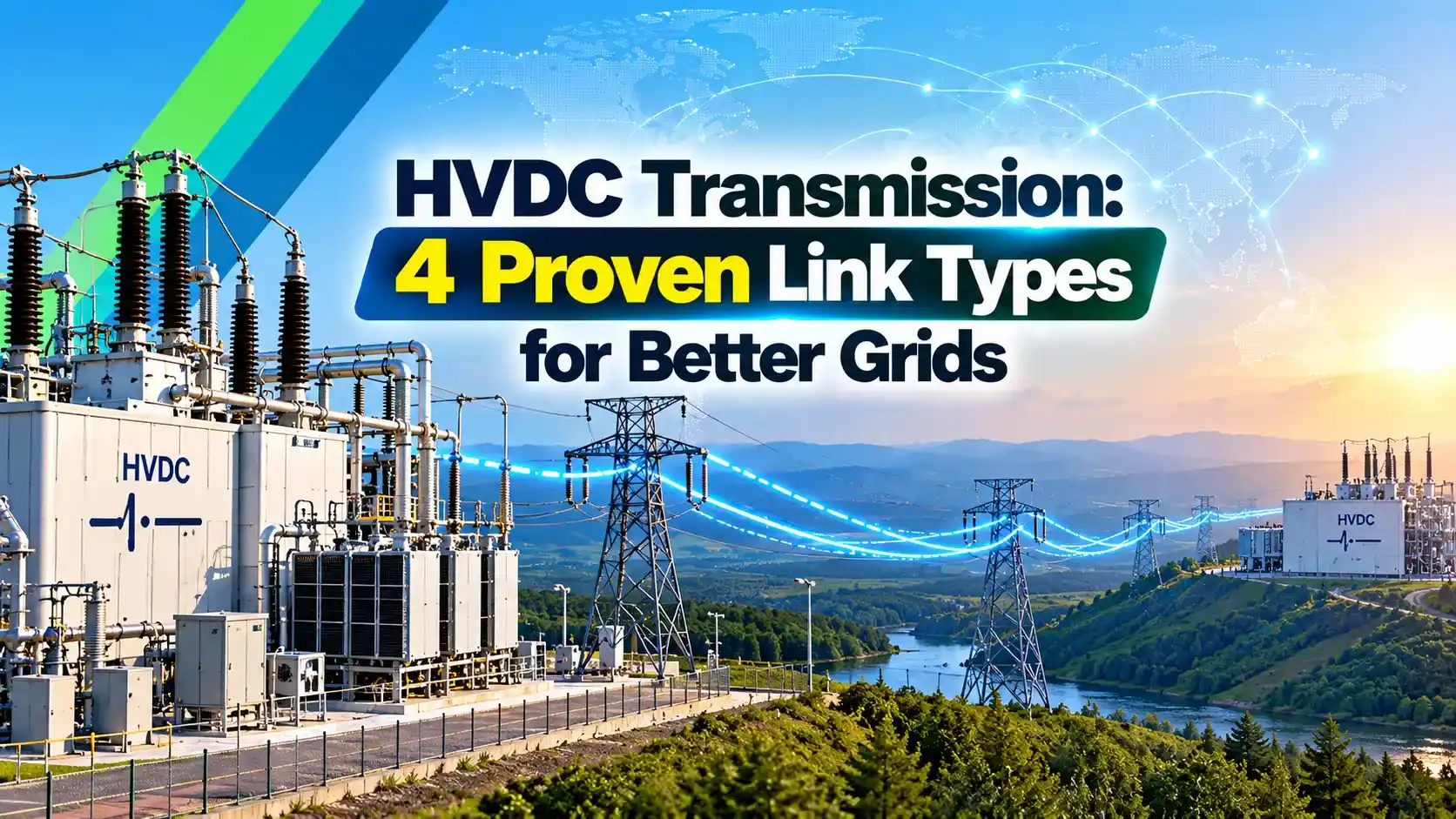
What Is HVDC Transmission?
HVDC transmission is the transfer of bulk electrical power using high voltage direct current, with a converter station at each end that turns AC into DC and back again. The basic contrast between the two forms of current is covered in difference between AC and DC.
The sending station works as a rectifier and the receiving station as an inverter, although both can swap roles when power flow reverses. The same ideas appear on a small scale in diode rectifier circuits and in a power inverter, but here each valve handles hundreds of kilovolts.
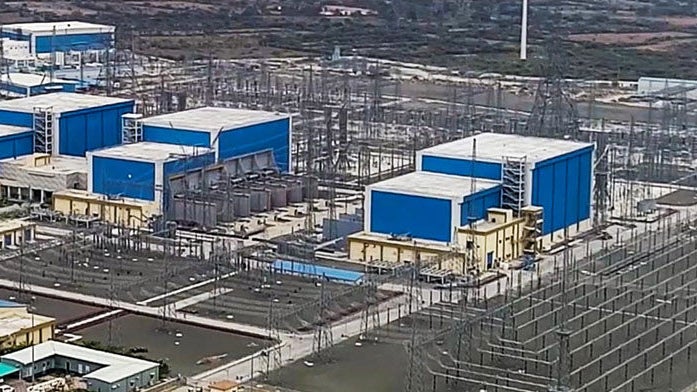
The line in HVDC transmission carries no reactive power and has no frequency, so its capacity is limited mainly by conductor heating and insulation. That makes HVDC transmission ideal for very long lines, submarine cables and links between unsynchronised grids.
Why HVDC Transmission Wins Over Long Distances
An AC line needs reactive power to charge its capacitance and suffers voltage rise at light load, the Ferranti effect. It also carries current mostly near the conductor surface because of the skin effect, while HVDC transmission uses the full conductor area.
A DC line needs only two conductors for a bipole instead of three for an AC circuit, so towers are lighter and corridors narrower. Against this saving, the converter stations are expensive, which leads to the idea of a break even distance.
National Grid explains that the longer the route, the more competitive HVDC transmission becomes, and that the break even distance can be several hundred kilometres depending on the installation. For overhead lines it is commonly quoted around 600 to 800 km, and for underground or submarine cables only about 50 to 100 km.
A long AC cable is so capacitive that its charging current alone can use up most of its thermal rating. That is why nearly every long submarine power cable in the world runs on direct current.
Inside an HVDC Converter Station
National Grid lists valves, converter transformers, harmonic filters, reactive compensation and smoothing reactors as the main parts of a line commutated station. The converter transformers use star and delta windings, similar to the transformer vector group idea, to build a 12 pulse bridge.
Switchyards at these stations are often indoor or gas insulated in tight sites, as discussed in GIS vs AIS substation. The valve hall itself is a climate controlled building with strict dust and humidity control.
LCC vs VSC in HVDC Transmission
Line commutated converters, LCC, use thyristor valves that turn on by a gate pulse and turn off only when the AC voltage reverses. Their working is explained in silicon controlled rectifiers, and each HVDC valve stacks many such devices in series.
Voltage source converters, VSC, use IGBT valves that can switch on and off at will, usually in a modular multilevel arrangement. This lets them control active and reactive power independently and even start a dead network.
| Feature | LCC | VSC |
|---|---|---|
| Valve device | Thyristor | IGBT |
| Reactive power | Consumes 50 to 60 % of rating | Controls it in both directions |
| Weak AC grid | Needs a strong grid | Works with weak grids |
| Power reversal | Reverse DC voltage polarity | Reverse current only |
| Black start | Not possible | Possible |
| Station footprint | About 200 m × 120 m | About 120 m × 60 m |
PSMA Consulting notes that LCC schemes reach power levels up to 6400 MW and need reactive power of about 50 to 60 percent of their rating. It also notes that VSC schemes can start or restore an AC network with no generators running, which LCC cannot do.
National Grid reports that a VSC station needs roughly 40 percent of the area of an LCC station of similar rating. That smaller footprint is a major reason VSC is chosen for offshore wind platforms and city infeeds.
When you study an LCC scheme, always check the short circuit ratio of the receiving grid first. A weak grid makes commutation failure likely and often pushes the design toward VSC.
4 Proven HVDC Transmission Link Configurations
One high voltage conductor with earth, sea or a metallic return.
Two poles of opposite polarity, each able to run alone at half power.
Rectifier and inverter in one station with no DC line.
Three or more stations on one DC system.
Most large HVDC transmission schemes in India are bipoles, because one pole can keep carrying power when the other trips. Back to back HVDC transmission stations were used earlier to join India regional grids before they were synchronised into one national grid.
DC Line Loss Formula
For a bipole, each pole carries current I = P ÷ (2 × Vd), where Vd is the pole to earth voltage. The copper loss of the line is then 2 × I² × R, with R the resistance of one pole conductor over the full length.
Line loss: Ploss = 2 × I² × r × L
r = DC resistance of one pole bundle in Ω per km, L = line length in km
Example:
P = 6000 MW, Vd = 800 kV, L = 1830 km, r = 0.006 Ω per km
I = 6000 ÷ 1.6 = 3750 A
R per pole = 0.006 × 1830 = 10.98 Ω
Ploss = 2 × 3750² × 10.98 = 308.8 MW
Loss = 5.15 % of rated power
The resistance value here is an illustrative figure for a multi conductor bundle, so use the actual conductor data for real studies. Converter losses of each station come on top of this line loss.
HVDC Transmission Line Loss Calculator
Second Worked Example: Why Voltage Matters
Keep the same 6000 MW and line, but reduce the pole voltage to 500 kV. The pole current rises to 6000 ÷ 1.0 = 6000 A, and the loss becomes 2 × 6000² × 10.98 = 790.6 MW, about 13.2 percent.
In HVDC transmission, the loss grows with the square of current, so raising voltage by 1.6 times cuts loss by about 2.56 times. This is the same logic that drives AC voltages upward, as seen in the per unit system studies used by grid planners.
HVDC Transmission Projects in India
| Link | Rating | Voltage | Length | Technology |
|---|---|---|---|---|
| Raigarh to Pugalur | 6000 MW | ±800 kV | 1830 km | LCC bipole |
| Champa to Kurukshetra | 6000 MW, four poles | ±800 kV | 1367 km | LCC with metallic return |
| Pugalur to Thrissur | 2000 MW | ±320 kV | Overhead and cable | VSC |
| Rihand to Dadri | 1500 MW | ±500 kV | About 800 km | LCC bipole |
Hitachi Energy reports that the Raigarh Pugalur link carries 6000 MW over 1830 km at ±800 kV and helps supply power to about 80 million people. It connects the western grid in Chhattisgarh to the southern grid in Tamil Nadu.
Power Line magazine reports that the Champa Kurukshetra scheme runs 1367 km, with each of its four poles rated 1500 MW for a total of 6000 MW. It was built by GE T&D India and is described as the first ±800 kV project in the world with a dedicated metallic return conductor.
BHEL made converter transformers, reactors and thyristor valves for the Raigarh Pugalur link in India. Its earlier HVDC work includes Rihand to Dadri, Chandrapur to Padghe and the Barsoor to Lower Sileru link.
HVDC Transmission Control and Harmonics
In an LCC scheme, the rectifier normally controls DC current by adjusting its firing angle, while the inverter holds a minimum extinction angle to avoid commutation failure. Power is set by the operator and the controls hold it steady regardless of AC angle changes.
Converters inject characteristic harmonics of order 12k ± 1 on the AC side for a 12 pulse bridge, so tuned filters are needed, as explained in power harmonics explained. These filters also supply part of the reactive power that an LCC station draws, a topic linked to active, reactive and apparent power.
Selecting LCC or VSC for a Project
- Compare route length with the break even distance for lines or cables.
- Check short circuit ratio of both AC grids.
- Decide whether black start or reactive support is needed.
- Estimate site area available for the converter station.
- Plan the return path, earth, sea or metallic.
- Include AC and DC filter needs in the budget.
- Review future multi terminal expansion plans.
If the receiving grid is weak or reactive support is needed, VSC is usually preferred, and it can act much like a large STATCOM at its terminals. Planners also check that any voltage sag and swell during AC faults will not trip the converter.
For student projects, simulate a simple 12 pulse LCC link before a VSC one. Seeing firing angle, DC current and AC harmonics change together teaches the fundamentals much faster.
- Lower line losses over long distances.
- Narrower corridors and lighter towers.
- Links grids of different frequency or phase.
- Fast and precise control of power flow.
- Very costly converter stations.
- Harmonics and filters at LCC stations.
- DC breakers are complex and costly.
- Tapping power midway is difficult.
Where HVDC Transmission Is Used
As India adds large solar and wind parks in Rajasthan, Gujarat and Ladakh, HVDC transmission corridors are planned to move this energy to load centres. Readers new to renewable integration can also study THD calculation in power systems for the power quality side.
National Grid HVDC Technical Information PDF
LCC and VSC Comparison Video
HVDC Transmission FAQ
It is the transfer of bulk power using high voltage direct current between two or more converter stations. The sending station rectifies AC to DC and the receiving station inverts it back.
It is used for long overhead lines, submarine cables and links between grids that are not synchronised. India uses it for large interregional corridors at ±800 kilovolts.
It is the route length beyond which HVDC transmission becomes cheaper overall than an AC link of the same capacity. The costly converter stations are offset by cheaper lines and lower losses.
For overhead lines it is commonly quoted around 600 to 800 kilometres. For cables it is much shorter, often only 50 to 100 kilometres, because of AC charging current.
An LCC station uses thyristor valves that turn off only when the AC voltage reverses. It handles the highest powers but needs a strong grid and large reactive support.
A VSC station uses IGBT valves that switch on and off at will. It controls reactive power, works with weak grids and can even black start a network.
A bipole has two conductors, one at positive and one at negative voltage with respect to earth. Normally the currents in both poles are equal, so little current flows in the return path.
If one pole trips, the other can keep running alone with an earth or metallic return. The link then carries roughly half of its full power.
The 12 pulse converter injects harmonic currents into the AC network at orders such as 11 and 13. Tuned AC filters absorb these harmonics and keep voltage distortion within limits.
The filters also supply a large share of the reactive power the converter draws. DC side filters and a smoothing reactor reduce ripple on the line as well.
Major Indian links include Raigarh to Pugalur and Champa to Kurukshetra, both rated 6000 megawatts at ±800 kilovolts. Older bipoles include Rihand to Dadri and Chandrapur to Padghe.
Pugalur to Thrissur is a 2000 megawatt VSC link serving Kerala in the south. Back to back stations were used earlier to join regional grids before national synchronisation.
A DC line carries no reactive current and has no skin effect, so the full conductor carries useful current. Two conductors can also carry the power that needs three conductors on an AC circuit.
Raising the pole voltage cuts current and therefore loss sharply. In the worked example, raising voltage 1.6 times reduced line loss by about 2.56 times.
Related Articles
- Difference Between AC and DC
- Silicon Controlled Rectifiers
- IGBT Working Principle and Applications
- Ferranti Effect in Transmission Lines
- Power Harmonics Explained
External References
- High Voltage Direct Current Electricity Technical Information, National Grid
- Raigarh Pugalur UHVDC Link, Hitachi Energy
- High Voltage Direct Current, Wikipedia
What We Learn Today
- HVDC transmission uses converter stations to turn AC into DC and back, giving lower losses and full control of power over very long routes.
- LCC uses thyristors and needs a strong grid with large reactive support, while VSC uses IGBTs and can control reactive power and black start networks.
- India runs ±800 kV bipoles such as Raigarh to Pugalur at 6000 MW over 1830 km and Champa to Kurukshetra with a metallic return.