
An on off valve that receives an open command has not necessarily opened, because air can fail, a shaft can shear or a solenoid can stick. A small switch enclosure on top of the actuator gives the control system honest proof of where the valve really is.
Every automated on off valve needs confirmation that it reached the commanded position. This guide explains how a limit switch box works, which switch to choose, how to mount and set it, and how to size the feedback timeout in the DCS.

What Is a Limit Switch Box?
A limit switch box is a compact enclosure mounted on top of a quarter turn valve actuator that senses the angular position of the actuator shaft and gives electrical open and closed signals to the control system. It also carries a visual indicator, so an operator walking past can see the valve state without a radio or a screen.
Inside are two or more switches operated by adjustable cams on a shaft that turns with the valve. Each switch works like the individual device described in what is a limit switch, but here the switches, terminals and indicator share one sealed housing.
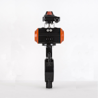
The typical host is a pneumatic rack and pinion or scotch yoke actuator, compared in scotch yoke vs rack and pinion actuator, on a ball or butterfly valve. The same enclosure often also carries the pilot solenoid or sits next to it on the actuator air port.
Inside the Enclosure: How Position Is Sensed
The actuator output shaft has a slot on top, and a coupler on the switch box spindle engages it so both turn together. Tameson notes that the limit switch box indicator is typically a coloured element seen through a clear window that moves with the valve stem.
Two cams sit on the spindle, one for the open end and one for the closed end of travel. Each cam is set so that its switch changes state only in the last few degrees of travel, which proves the valve really reached its seat or its full open stop.
Festo specifies its SRBE box with an angular detection setting range of 0 to 90 degrees and trip cams that can be set without additional tools. That tool free adjustment is now common because it saves time at every loop check.
Switch Choices in a Limit Switch Box
A lever or roller contact snaps over as the cam lobe passes, giving a dry SPDT contact.
A non contact sensor detects a metal cam target, with PNP, NPN or 2 wire output.
A 2 wire sensor whose current changes with the target, used with an isolating amplifier.
Sealed reed contacts operated by a magnet on the spindle.
An AS Interface or DeviceNet board replaces discrete wiring and also drives the solenoid.
Mechanical microswitches are cheap and easy to test with a multimeter, but their contacts wear and can bounce. Non contact types avoid wear, and the choice between them follows the rules in inductive proximity sensor selection and NPN and PNP proximity sensors.
Reed versions use a magnet instead of a steel target, which suits the principle explained in reed switch working principle. Always check the DI card type, sinking or sourcing, before you order the switch output, as described in sinking and sourcing in PLC.
NAMUR Sensors and Intrinsically Safe Wiring
A NAMUR sensor has no switching transistor; it behaves like a variable resistance that draws more or less current from an 8.2 V source through about 1 kΩ. The isolating amplifier reads a low current, below about 1.2 mA, as damped and a higher current, above about 2.1 mA, as undamped, as covered in NAMUR output sensor.
| Loop State | Approximate Current | Amplifier Reading |
|---|---|---|
| Target present, damped | Below 1.2 mA | One logic state |
| Target absent, undamped | Above 2.1 mA | Opposite logic state |
| Cable broken | Near zero | Line fault alarm |
| Cable shorted | Well above normal | Line fault alarm |
NAMUR wiring therefore gives better diagnostics than a simple dry contact. The amplifier also provides the barrier function, and the design choices are compared in explosion proof vs intrinsically safe instruments.
Enable line fault detection on the isolating amplifier for every NAMUR channel. Without it, a cut cable looks exactly like a valve that has left its end position.
VDI/VDE 3845 Mounting Interface
VDI/VDE 3845, usually called the NAMUR interface, fixes the hole pattern, shaft slot and shaft height on top of the actuator. Tameson reports that its switch boxes accommodate hole patterns of 80 × 30 mm and 130 × 30 mm, the two common sizes on quarter turn actuators.
Festo lists stainless steel mounting brackets for 30 × 80 mm and 30 × 130 mm patterns, with shaft heights of 20 mm and 30 mm. Match the bracket height to the actuator shaft height, or the coupler will bind or slip.
The same standard defines the solenoid port face on the actuator side, which lets a solenoid valve bolt directly on. Correct valve fail action, explained in fail safe valve positions, must be confirmed together with the switch settings.
Feedback Timeout Formula
The DCS starts a timer when it sends an open or close command and raises a discrepancy alarm if the matching switch does not arrive in time. The timer must be longer than the real stroke time but short enough to catch a stuck valve quickly.
Switch life in years = Rated operations ÷ (Cycles per day × 365)
Example:
Measured stroke time 8 s, margin 50 %, scan and filter delay 0.5 s
Timeout = 8 × 1.5 + 0.5 = 12.5 s
Rated operations 1000000, 100 full cycles per day
Life = 1000000 ÷ (100 × 365) = 27.4 years
Set 12.5 s timeout, switch life about 27.4 years
Measure stroke time at site air pressure, since long tubing and small solenoid ports slow a large actuator. The DI card filter time adds to the delay, so check it in the card settings listed in DCS I/O card types.
Valve Feedback Timeout and Switch Life Calculator
Second Worked Example: Fast ESD Valve
An emergency shutdown ball valve has a measured closing time of 3 s, and the safety engineer wants a 100 percent margin with a 0.25 s scan delay. The timeout becomes 3 × 2 + 0.25 = 6.25 s, far shorter than the default of a slow utility valve, which suits an emergency shutdown system.
7 Essential Steps to Mount and Set the Switches
Never set the cams with the valve only close to its end stop, because a partly open valve would then report closed. Loop verification follows the method in instrument loop checking procedure, with the limit switch box state checked locally and on the operator graphic.
Turn the manual override or use a hand pump to move the actuator slowly while setting cams. Setting against a fast pneumatic stroke almost always leaves the switch point a few degrees off.
Enclosure and Hazardous Area Selection
Most process duty limit switch box housings are die cast aluminium or stainless steel with an IP67 rating, and Festo also quotes NEMA 4 and 4X. The meaning of those codes is explained in IP rating explained.
In classified areas, choose either a flameproof Ex d housing or intrinsically safe NAMUR sensors in a simpler enclosure. Zone, gas group and temperature class must match the site study, as described in hazardous area classification zones and gas groups IIA, IIB and IIC.
- Ex marking, zone, gas group and temperature class match the area.
- IP rating suits washdown, rain or coastal exposure.
- Switch output matches the DI card, contact, PNP, NPN or NAMUR.
- Bracket fits the actuator hole pattern and shaft height.
- Cable entry thread, M20 or 1/2 NPT, matches the glands.
Some switch box models include an AS Interface module that reads both switches and drives the pilot solenoid over one two core cable. A skid with dozens of valves then needs far fewer cores back to the control panel.
Where Valve Position Switches Are Used
Limit Switch Box Fault Finding
| Symptom | Likely Cause | Remedy |
|---|---|---|
| Both open and closed signals on | Cam overlap or shorted cable | Reset cams, test cable insulation |
| Neither signal at an end position | Cam slipped or valve short of stop | Check travel, retighten cam |
| Feedback flickers | Loose coupler or vibration | Tighten coupler, consider proximity switches |
| Water inside housing | Unsealed entry or damaged O ring | Replace gland, plug and seal |
Moisture is the most common field problem, especially after the monsoon in Indian plants. Wiring checks should follow the marshalling cabinet wiring so that faults are traced from both ends.
- Confirms the real valve position to the DCS.
- Local indicator visible from a distance.
- Standard NAMUR mounting on most actuators.
- Choice of mechanical, proximity and NAMUR switches.
- Gives only end positions, not travel.
- Cams and couplers can slip.
- Moisture ingress causes false signals.
- Ex certified versions cost more.
Switch Box or Positioner Feedback?
A modulating control valve uses a positioner with a 4 to 20 mA position transmitter, as shown in control valve positioner working. An on off valve needs only end position proof, so a limit switch box is simpler and cheaper for that duty.
Festo SRBE Switch Box Documentation
Mounting a Switch Box Video
Limit Switch Box FAQ
It senses the open and closed end positions of a quarter turn valve and sends matching electrical signals to the control system. It also shows the valve state locally through a coloured indicator on the cover.
The DCS uses these signals for interlocks, sequences and discrepancy alarms. Without them the system only knows what it commanded, not what really happened.
Common choices are mechanical microswitches, inductive proximity sensors, NAMUR sensors and magnetic reed switches on the same cam spindle. Some models carry an AS Interface or DeviceNet module instead of discrete switches.
The choice depends on the DI card, the cycle rate and the hazardous area rating. High cycle or vibrating valves usually benefit from non contact sensors that never wear.
It is the NAMUR interface standard that fixes the bracket hole pattern, shaft slot and shaft height on top of an actuator. Common hole patterns are 80 by 30 mm and 130 by 30 mm.
Because the interface is standard, one switch box model fits actuators from many makers. Only the bracket height needs to match the shaft height on site.
Move the valve slowly to the fully closed stop and turn the closed cam until its switch just changes state. Then move the valve fully open and repeat for the open cam.
Lock both cams and stroke the valve several times to confirm repeatable signals. Always check the states locally and on the operator screen before sign off.
A NAMUR sensor works with an intrinsically safe isolating amplifier supplied at about 8.2 volts. It gives a low current when damped and a higher current when undamped.
The amplifier can also detect a broken or shorted cable as a line fault. This makes it a good choice for Zone 1 and Zone 2 valves with safe diagnostics.
Measure the real stroke time at site air pressure, then add a margin of about 50 to 100 percent. Finally add the DI filter and controller scan delay to that figure.
For an 8 s stroke with 50 percent margin and 0.5 s delay, the timeout is 12.5 s. Fast shutdown valves need a shorter and tighter value.
Moisture usually enters through an unsealed cable entry, a missing stopping plug or a damaged cover O ring. Top entry cables let rainwater run straight into the terminals.
Use certified glands, plug every spare entry and bring cables in from below with a drip loop. Check the cover seal at every shutdown and replace it when hard.
Related Articles
- What Is a Limit Switch
- NAMUR Output Sensor
- Solenoid Valve Working Principle
- Scotch Yoke vs Rack and Pinion Actuator
- Partial Stroke Testing of ESD Valves
External References
- Limit Switch Box SRBE Documentation, Festo
- Improve Efficiency with Limit Switch Boxes, Tameson
- Limit Switch, Wikipedia
What We Learn Today
- A limit switch box sits on a quarter turn actuator and uses cams and switches to report the open and closed valve positions to the DCS.
- Switch options include mechanical microswitches, inductive proximity sensors, NAMUR sensors with isolating amplifiers, magnetic reed switches and fieldbus modules for large valve skids.
- Correct cam setting, sealed cable entries, matching Ex certification and a sensible feedback timeout make valve position signals reliable for interlocks and sequences.