
Every thermocouple slowly changes once it sees heat, and the only way to know how far it has moved is to compare it with a trusted reference. This guide walks you through a practical, audit ready method used in plants and labs.
A thermocouple can read several degrees wrong without any alarm in the control room. A planned thermocouple calibration with a reference PRT, correct immersion and a clear uncertainty budget tells you exactly how much to trust each reading.

What Is Thermocouple Calibration?
Thermocouple calibration is the process of comparing the output of a thermocouple, in millivolts or in degrees, with a traceable reference at known temperatures and recording the difference as an error or correction. It does not adjust the sensor itself, it tells you how far the reading is from the true temperature.
A thermocouple produces a small voltage because two different metals are joined, a principle explained in basics of thermocouples and RTD. The voltage depends on the metal pair, so each type in types of thermocouples and ranges has its own reference table.
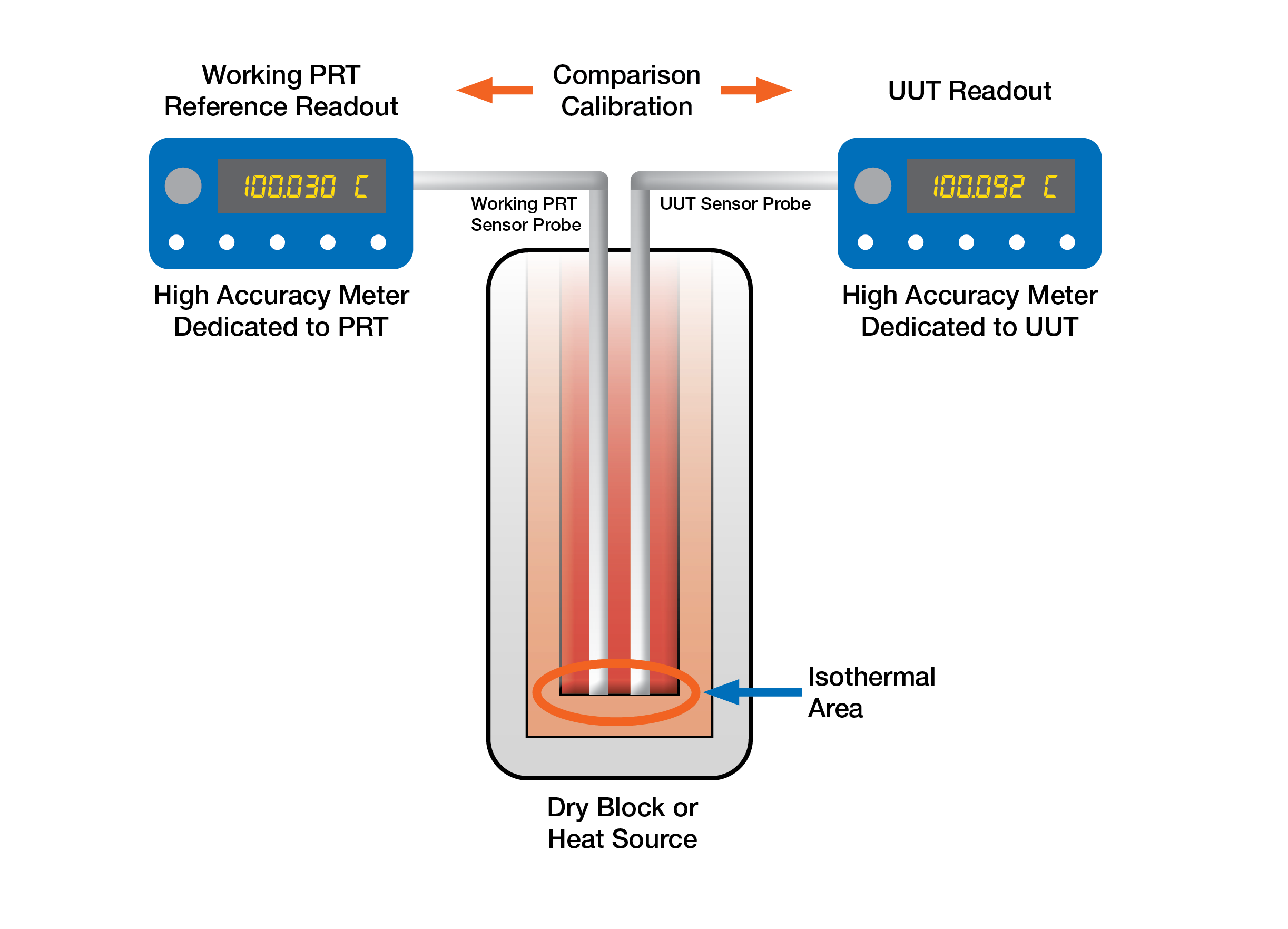
Ashcroft explains that the comparison is made against a traceable working PRT placed in the same isothermal zone of a dry block, at defined temperatures. Ashcroft also stresses that thermocouple calibration only identifies error, because the material changes inside the wires are permanent.
Why Thermocouple Calibration Is Needed
Ashcroft notes that a correctly configured thermocouple in a moderate environment can give useful service for five to ten years or longer. At around 900 °C and above, drift speeds up as chromium diffuses between the conductors and the millivolt output falls.
Drift is silent, because the loop still shows a believable number, which is why the errors listed in temperature measurement errors must be checked on a schedule and not only after a complaint.
The voltage of a thermocouple is generated along the length of wire that sits in a temperature gradient, not at the tip. That is why a used thermocouple can read differently when it is inserted to a new depth.
TC Ltd, a UKAS accredited laboratory, states that thermocouple calibration is usually performed once a year and more often in harsh service. The right interval for your plant should be set from history, as described in calibration interval determination.
Methods of Thermocouple Calibration
The thermocouple and a reference PRT sit side by side in a metal block heated to set points.
A liquid bath of oil, water or salt gives better uniformity than a block.
Pure metals freeze or melt at ITS 90 temperatures such as zinc at 419.527 °C.
A reference sensor is inserted next to the installed thermocouple in the process.
TC Ltd describes fixed point calibration as the most accurate but limited to a few temperatures, while the comparison method in stirred baths or furnaces is the most popular. Most plant technicians use a portable dry block calibrator, and the choices are compared in types of temperature calibrators.
Use a dry block insert with a bore only slightly larger than the probe, and add a few drops of the right heat transfer medium only if the manufacturer allows it. An air gap of even half a millimetre adds lag and error.
Thermocouple Calibration Tolerance Classes
| Standard and Class | Type K or N Tolerance | Type J Tolerance | Note |
|---|---|---|---|
| IEC 60584 Class 1 | ±1.5 °C or ±0.004 × |t| | ±1.5 °C or ±0.004 × |t| | Larger value applies |
| IEC 60584 Class 2 | ±2.5 °C or ±0.0075 × |t| | ±2.5 °C or ±0.0075 × |t| | Most common in plants |
| ASTM E230 Special | ±1.1 °C or ±0.4 percent | ±1.1 °C or ±0.4 percent | Above 0 °C |
| ASTM E230 Standard | ±2.2 °C or ±0.75 percent | ±2.2 °C or ±0.75 percent | Above 0 °C |
For each class, the allowed error is the larger of the fixed value and the percentage of the measured temperature. A Type K Class 2 sensor at 400 °C may therefore be off by up to 3.0 °C, because 0.0075 × 400 is larger than 2.5.
Thermocouple Calibration Equipment Checklist
- Reference PRT with a valid, traceable certificate and its coefficients.
- Dry block or bath with known stability and axial uniformity.
- Readout or calibrator able to measure thermocouple millivolts and the reference resistance.
- Correct thermocouple extension or compensating cable, checked for polarity.
- Ice point or a characterised cold junction method for the reference junction.
- Calibration sheet with test points, acceptance limits and as found columns.
- Insulating gloves, tongs and a safe place to cool hot probes.
A multifunction process calibrator can read both sensors and document the whole run. Handle the reference PRT gently, as described in the Pt100 RTD calibration guide.
Thermocouple Calibration Procedure in 7 Steps
Fluke Calibration recommends that probes be immersed to a depth equal to 15 times the probe diameter plus the length of the sensing element. Fluke also advises placing several probes in a radial pattern with the reference probe in the centre to reduce gradient effects.
Run the points in rising order and note the time of each reading. The as found and as left results feed the correction factor in calibration that the plant may apply in the DCS or transmitter.
When the thermocouple is used with a head mounted transmitter, calibrate the sensor and the transmitter as a loop, or trim the transmitter with the sensor errors. Checking them separately can hide a combined error that exceeds the limit.
Cold Junction Compensation During Calibration
A thermocouple measures the difference between the hot junction and the reference junction, so the reference end must be known. The theory is explained in cold junction compensation in thermocouple, and it is the most common hidden source of error in thermocouple calibration.
Fluke Calibration notes that internal reference junctions in readouts suit high throughput work, with a typical additional uncertainty of about 0.05 to 0.25 °C. For the best results, the reference junction is held in an ice point at 0 °C and the raw millivolts are converted with the standard table.
Wrong extension cable or reversed polarity gives errors that change with ambient temperature. Confirm the wire colours with thermocouple polarity identification and use the correct grade of thermocouple extension wire up to the readout.
Error Formula and Pass or Fail Logic
Allowed limit L = larger of a and (b × |T reference|)
Pass when |E| is less than or equal to L
Example, Type K Class 2:
T reference = 400.0 °C, T thermocouple = 401.8 °C
E = 401.8 minus 400.0 = 1.80 °C
b × |t| = 0.0075 × 400 = 3.00 °C, a = 2.5 °C
L = 3.00 °C, so the sensor passes
The same logic works for any class if you change a and b, for example a = 1.5 and b = 0.004 for Class 1.
Thermocouple Calibration Error Calculator
Second Worked Example: Simple Uncertainty Budget
Suppose a lab checks a Type N sensor at 600 °C with an assumed reference PRT uncertainty of 0.05 °C, block uniformity of 0.15 °C, readout uncertainty of 0.10 °C and CJC uncertainty of 0.20 °C, all as standard uncertainties. The combined value is the square root of the sum of squares, which is about 0.28 °C.
Multiplying by a coverage factor of 2 gives an expanded uncertainty of about 0.56 °C at roughly 95 percent confidence. The method is explained in measurement uncertainty in calibration, and a lab accredited under ISO 17025 must state it on every certificate.
Inhomogeneity and Immersion in Thermocouple Calibration
When a thermocouple has been used, the part of the wire that sat in the hot zone changes, while the cooler part stays almost new. If the sensor is calibrated at a different depth than it was installed, the gradient falls on a different section of wire and the result no longer represents the process.
For this reason many plants limit lab checks to new or reference sensors and simply replace used base metal ones. Practical ways to reduce such errors are shared in improve thermocouple accuracy.
The ITS 90 scale defines its fixed points with very high accuracy, for example the freezing point of zinc at 419.527 °C and of aluminium at 660.323 °C. National labs use these cells to calibrate the reference thermocouples that plants rely on.
Troubleshooting a Failed Thermocouple Calibration
| Symptom | Likely Cause | Action |
|---|---|---|
| Error drifts while reading | Block not stable or probe not at temperature | Wait longer, check stability spec |
| Error changes with depth | Inhomogeneity or stem conduction | Check immersion, replace used sensor |
| Same offset at all points | CJC or wrong cable type | Check reference junction and wiring |
| Error grows with temperature | Drift of the wire or wrong type selected | Confirm type, replace if beyond limit |
| Low insulation resistance | Moisture in sheath | Dry, retest or replace |
If the readings jump or show open circuit, check the junction and the thermocouple burnout detection setting in the receiver. A sensor that passes on the bench but fails in service often points to installation, as explained in thermocouple and RTD installation precautions.
- Reveals silent drift before it affects product or safety.
- Gives documented, traceable evidence for audits.
- Supports correction factors in the control system.
- Builds history to optimise calibration intervals.
- Cannot restore a drifted sensor to new condition.
- Bench result may not match in situ gradients.
- High temperature points take time and energy.
- Field equipment uncertainty limits accuracy.
Where Thermocouple Calibration Matters Most
In each case, the sensor check is followed by a loop check, as described in how to calibrate a temperature transmitter.
Fluke Application Note on Thermocouple Calibration
Thermocouple Calibration Video Demonstration
Thermocouple Calibration FAQ
It is the comparison of a thermocouple output with a traceable reference at known temperatures. The difference is recorded as an error or a correction value.
It does not adjust or repair the sensor wire in any way. It simply tells you how far the reading is from the true temperature at each test point.
Most plant and lab work uses a working platinum resistance thermometer with a traceable certificate. It is far more stable than a base metal thermocouple at the same temperature.
Above roughly 660 °C, a calibrated Type S or Type R thermocouple is often used instead. The reference must always carry a valid certificate and a known uncertainty.
Use at least three points that cover the working range of the sensor. Add one point close to the normal operating temperature of the process.
Fluke Calibration notes that a sensor should be calibrated over the full range in which it is used. Never extrapolate the results far beyond the highest point that was tested.
Fluke Calibration recommends at least 15 times the probe diameter plus the sensing element length. A 6 mm probe with a 10 mm element therefore needs about 100 mm.
Too little immersion lets heat flow along the sheath and gives a stem conduction error. Check stability by raising the probe slightly and watching for any change.
The wire that sat in the hot zone has changed, while the cooler section is still almost new. This uneven condition is called inhomogeneity, and it grows with time at high temperature.
During thermocouple calibration in the lab, the gradient falls on a different part of the wire, so the result can differ. Many plants therefore replace used base metal sensors instead of recalibrating them.
TC Ltd notes that yearly checks are common, with shorter intervals in harsh service. Above about 900 °C, drift speeds up and checks should be more frequent.
Ashcroft points out that there is no universal schedule for every plant. Set the interval from your own as found history, process risk and any quality or regulatory needs.
IEC 60584 Class 2 allows 2.5 °C or 0.75 percent of the temperature, whichever is larger. Class 1 allows 1.5 °C or 0.4 percent of the temperature.
Many plants also set a tighter internal limit for important loops, batch reactors and furnaces. Always write the limit on the thermocouple calibration sheet before the test begins.
Related Articles
- Dry Block Calibrator
- Cold Junction Compensation in Thermocouple
- Measurement Uncertainty in Calibration
- Pt100 RTD Calibration Guide
- Types of Temperature Calibrators
External References
- How to Calibrate a Thermocouple, Application Note, Fluke Calibration
- How to Perform a Thermocouple Calibration and Why it Matters, Ashcroft
- Thermocouple, Wikipedia
What We Learn Today
- Thermocouple calibration compares the sensor with a traceable reference PRT at several points and records the error, it never repairs drift in the wire.
- Immerse the probe at least 15 diameters plus the element length, centre the reference, and allow 10 to 20 minutes for each point to settle.
- Pass or fail uses the larger of a fixed limit and a percentage, so a Type K Class 2 sensor at 400 °C allows 3.0 °C.