
A V-Cone flow meter measures flow the same way an orifice plate does, by creating a pressure drop, but the way it creates that drop, from the center of the pipe outward, is what lets it work in tight spaces where other differential pressure meters simply can't.
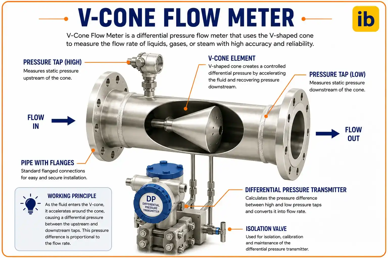
The V-Cone flow meter working principle relies on a centrally mounted cone that reshapes the velocity profile and creates a measurable pressure drop, letting it deliver accurate flow readings with almost no straight pipe run.
Like the orifice plate and the Venturi tube before it, the V-Cone is a differential pressure, or DP, meter. All DP meters work on the same underlying physics: an obstruction in the pipe reduces the cross-sectional area available to the flow, the flow speeds up through that reduced area, and Bernoulli's theorem says pressure has to drop wherever velocity rises. Measure that pressure drop, know the fluid density, and the flow rate falls straight out of the math.

What makes the V-Cone different is where the obstruction sits and how it's shaped. Instead of a flat plate with a hole in the middle, a V-Cone places a cone-shaped element in the center of the pipe, pointing upstream, so the flow squeezes through an annular ring around the outside of the cone rather than through a central bore. That single geometry change is responsible for nearly every practical advantage the V-Cone has over older DP meter designs.
How Flow Passes Through a V-Cone Flow Meter
Understanding the V-Cone flow meter working principle step by step makes it obvious why the design behaves so differently from a plate with a hole in it.
Flow Approaches the Cone
Fluid enters the meter at line pressure P1, moving at the pipe's normal average velocity.
Cone Reshapes the Profile
The cone's contour smooths out swirl and uneven velocity before the flow even reaches its widest point.
Flow Squeezes Through the Ring
The annular gap between the cone and the pipe wall forces flow to accelerate through a smaller area.
Pressure Drops to P2
Following Bernoulli's principle, the higher velocity at the constriction corresponds to a lower static pressure.
DP Converts to Flow Rate
A transmitter reads P1 minus P2, and the beta ratio and discharge coefficient convert that reading into flow rate.
Two Tap Designs: Cone Tap vs Wall Tap
The V-Cone flow meter working principle also depends on how the low-pressure tap is taken, and manufacturers offer two arrangements depending on the fluid.
Cone Tap Design
The low-pressure port sits on the downstream face of the hollow cone itself, right where the pressure recovery is most predictable. This gives the strongest, most repeatable DP signal.
Wall Tap Design
The cone is sealed and the low-pressure reading is instead taken through a port in the pipe wall downstream of the cone, avoiding any risk of the internal cone passage clogging.
Understanding the V-Cone Beta Ratio
Every DP meter has a beta ratio, but the V-Cone calculates it differently from an orifice plate or Venturi tube because there's no simple central bore to measure.
The beta ratio equals the flow area at the largest cross section of the cone, converted to an equivalent diameter, divided by the meter's inside diameter. A higher beta ratio means more open area and a smaller pressure drop for the same flow rate.
Beta Ratio and Flow Rate Formula
The beta ratio for a V-Cone is derived from the open annular area at the cone's largest cross section, then plugged into the same general DP flow equation used across orifice, Venturi, and cone-type meters.
d = largest cone diameter,
D = meter inside diameter Example: d = 6 in, D = 10 in Beta = sqrt(1 - (6/10)^2)
= sqrt(1 - 0.36)
= sqrt(0.64)
= 0.80
Cd = discharge coefficient,
Ev = velocity of approach factor = 1/sqrt(1 - Beta^4) Example: D = 0.254 m, Beta = 0.65, Cd = 0.82, DP = 15000 Pa, rho = 1000 kg/m3 Ev = 1/sqrt(1 - 0.65^4)
= 1/sqrt(0.821)
= 1.104 Q = 0.82 x 1.104 x 0.785 x (0.65 x 0.254)^2 x sqrt(2 x 15000/1000) Q = approximately 0.0715 m3/s
V-Cone vs Orifice Plate vs Venturi Tube
The clearest way to see why the V-Cone flow meter working principle matters in practice, and why it's worth understanding before specifying one, is to line it up directly against the two older DP meter designs it's most often compared to.
| Property | Orifice Plate | Venturi Tube | V-Cone |
|---|---|---|---|
| Upstream straight run needed | 10 to 30 pipe diameters | 5 to 20 pipe diameters | 0 to 3 pipe diameters |
| Typical accuracy | ±1 to 2% of rate | ±0.75 to 1.5% of rate | ±0.5% of rate |
| Permanent pressure loss | High | Low | Low |
| Turndown ratio | Around 3:1 to 5:1 | Around 4:1 to 6:1 | 10:1, up to 40:1 |
| Sensitivity to swirl and disturbance | High | Moderate | Low, self-conditioning |
Where V-Cone Flow Meters Are Typically Installed
Oil and Gas
Wellhead, custody transfer, and gas lift measurement in tight skid layouts.
Wet and Superheated Steam
Handles two-phase and high-temperature steam flows other DP meters struggle with.
Cryogenic Service
LNG and other cryogenic coolant flows in compact liquefaction skids.
Municipal Water
Retrofit metering where little to no straight-run pipe is available.
Chemical Processing
Corrosive and hazardous chemical flows needing minimal maintenance.
Wet Gas Measurement
Gas streams carrying liquid droplets, common in upstream production.
Advantages and Limitations of the V-Cone Design
✓ Advantages
- Needs almost no straight upstream or downstream pipe run
- Self-conditioning, so it tolerates swirl and disturbed flow profiles
- Wide turndown ratio compared to orifice plates and Venturi tubes
- Low permanent pressure loss and a service life beyond 25 years
✗ Limitations
- Higher unit cost than a simple orifice plate
- Cone tap design can be prone to clogging in dirty fluid unless a wall tap is specified
- Larger sizes and higher beta ratios may need custom calibration
- Cd is generally determined by calibration rather than a universal published table
Discharge Coefficient and Calibration in the V-Cone Flow Meter Working Principle
Unlike an orifice plate, where the discharge coefficient can often be taken from a published ISO 5167 table for a standard sharp-edged design, the V-Cone's discharge coefficient is generally established through wet or dry calibration at a certified flow laboratory. The cone's unconventional geometry means Cd doesn't follow the same universal empirical equations that decades of orifice plate testing produced.
In practice this isn't as inconvenient as it sounds. Manufacturers calibrate each meter design and beta ratio combination against traceable reference standards, and the resulting Cd typically holds within a tight band, often around 0.82 to 0.84, across a wide Reynolds number range. That flat, predictable Cd curve is actually one of the reasons V-Cone meters achieve such a wide turndown ratio without needing a new calibration for every flow condition.
Installation and Material Considerations
A V-Cone flow meter is typically supplied as a spool piece with the cone welded or bolted in place, ready to install between two flanges like any other inline meter. Because it needs so little straight pipe, it fits into retrofit projects and skid packages where an orifice plate run or a Venturi tube section simply wouldn't have room.
Material selection follows the same logic as any other wetted process instrument: carbon steel and stainless steel cover most water, oil, and gas services, while more exotic alloys like Hastelloy or Inconel get specified for sour gas, highly corrosive chemicals, or extreme cryogenic temperatures. Because the cone has no moving parts, wear is limited to erosion from abrasive particles at the leading edge, which is one of the reasons V-Cone meters are rated for a service life beyond 25 years with essentially no routine maintenance.
Live V-Cone Flow Rate Calculator
Enter the pipe diameter, beta ratio, differential pressure, discharge coefficient, and fluid density to estimate volumetric flow rate using the standard DP flow equation.
Reference Materials on V-Cone Flow Meters
FAQs on V-Cone Flow Meter Working Principle
Why the V-Cone Acts as Its Own Flow Conditioner
Most DP meters need a long, straight, undisturbed run of pipe upstream because any swirl or asymmetric velocity profile coming out of an elbow, tee, or partly open valve distorts the reading. An orifice plate has no way to correct for that distortion on its own, so the only fix is distance, giving the flow enough straight pipe to settle down before it reaches the plate.
The V-Cone sidesteps that requirement almost entirely. Because the cone sits in the center of the pipe and forces flow through a symmetric annular ring, it physically remixes and re-centers the velocity profile as part of the measurement itself. Independent testing by facilities like the Southwest Research Institute has repeatedly shown the meter holding its rated accuracy with as little as zero to three diameters of straight pipe upstream, a fraction of what an orifice plate or even a Venturi tube needs.
Choosing the Right Beta Ratio for a V-Cone Installation
Beta ratio selection on a V-Cone works the same way it does on any DP meter: a lower beta ratio creates a bigger, easier-to-read differential pressure signal but also a bigger permanent pressure loss, while a higher beta ratio does the opposite. Standard V-Cone beta ratios run from 0.45 up to 0.80, and the right choice depends on the available differential pressure range of the transmitter and the acceptable pressure loss for the process.
Two limits matter most when narrowing that choice down. In liquid service, the beta ratio should never be selected in a way that lets the static line pressure minus the differential pressure fall below the fluid's vapor pressure, since that risks cavitation right at the measurement point. In gas or vapor service, the beta ratio needs to keep the gas expansion factor above roughly 0.84, which in practice limits how aggressive a differential pressure can be specified for compressible flows.
Related articles on this site
External References
- What Is A V-Cone Meter? And Why Should I Care?, McCrometer
- Not All Differential Pressure Meters Are Created Equal, McCrometer
- Permanent Pressure Loss Comparison Among Various Flowmeter Technologies, McCrometer
- V-Cone Flow Meter Product Brochure, McCrometer
- Tests of the V-Cone Flow Meter per API Test Protocol, Southwest Research Institute
What we learn today
- The V-Cone flow meter working principle is the same Bernoulli-based DP physics as an orifice plate or Venturi, applied through a centrally mounted cone instead of a plate or converging tube.
- The V-Cone beta ratio is calculated from the annular open area around the cone, using Beta = sqrt(1 minus (d/D) squared), not a simple bore-to-pipe ratio.
- The cone's shape acts as a built-in flow conditioner, cutting straight-run requirements to as little as 0 to 3 pipe diameters versus 10 to 30 for an orifice plate.
- Cone tap and wall tap designs let the same basic meter handle both clean fluids and dirty, solids-laden flows.
- Typical accuracy of plus or minus 0.5 percent of rate, a wide turndown ratio, and low permanent pressure loss make V-Cones a strong fit for oil and gas, wet gas, steam, and retrofit water metering.