
Flow Measurement · Orifice Plate · ISO 5167 · Discharge Coefficient
How Orifice Plate Thickness Affects Performance: 5 Critical Factors Every Engineer Must Verify
Orifice plate thickness looks like a minor mechanical detail, but it directly determines the discharge coefficient accuracy, the structural integrity under differential pressure, and whether your flow measurement is even valid under ISO 5167. This guide explains exactly how orifice plate thickness affects performance, the bore-to-thickness ratio rule, edge sharpness requirements and a live plate thickness calculator.
Why Orifice Plate Thickness Affects Flow Measurement Performance
The standard orifice plate discharge coefficient equations in ISO 5167 and the older AGA-3 standard are derived assuming a specific plate geometry: a sharp-edged, thin plate with a bevelled downstream face. Orifice plate thickness affects performance because the discharge coefficient (Cd) used in every flow calculation is only valid within a defined plate thickness range relative to the bore diameter. Deviate outside this range and the actual flow coefficient diverges from the published value, introducing measurement error that no amount of careful installation elsewhere can correct.
This matters because orifice plates remain the most widely used differential pressure flow measurement device in industry, and plate thickness is one of the few geometric parameters fully within the fabricator's and engineer's control at the design stage.
ISO 5167 Orifice Plate Thickness Limits Formula
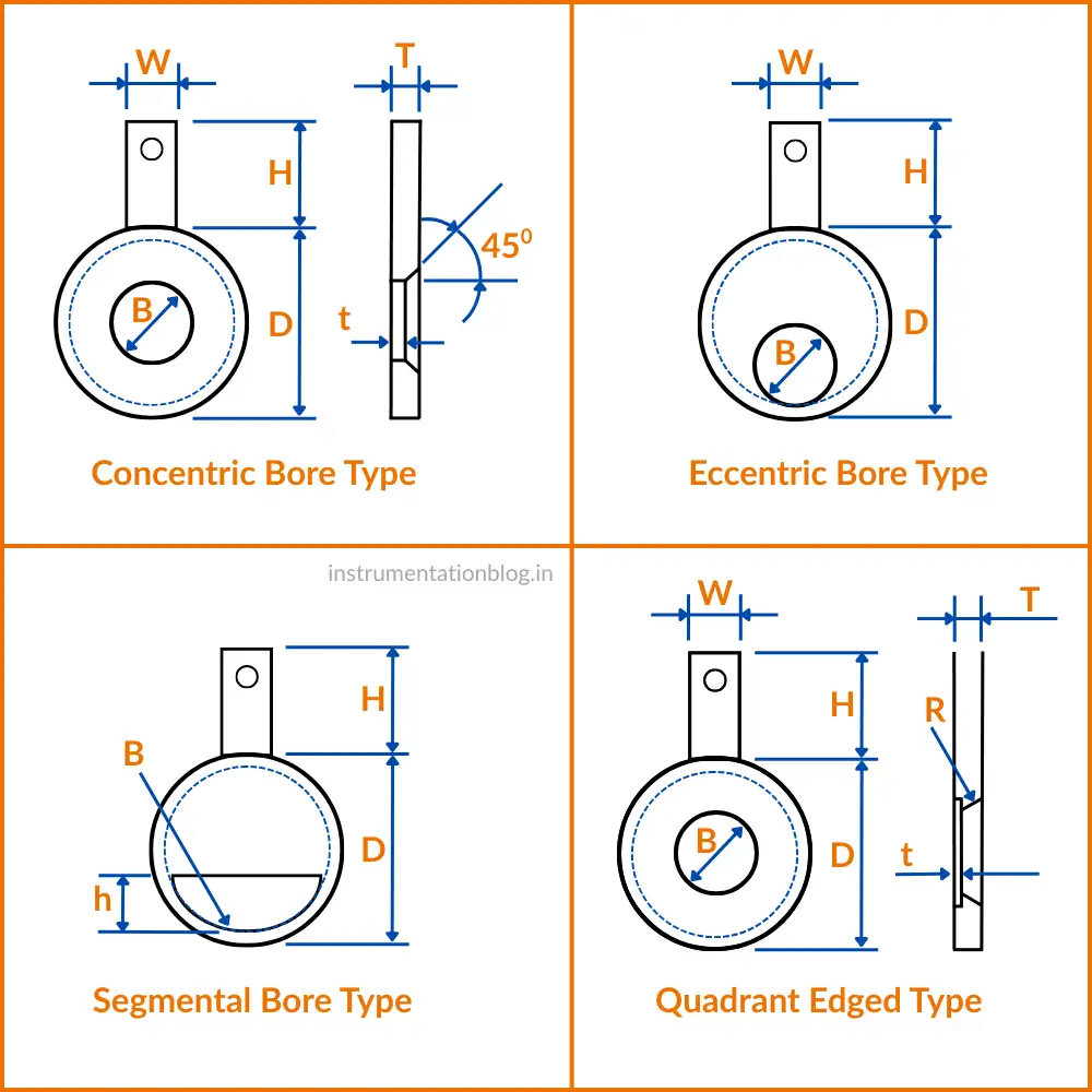
Plate thickness: 0.005D <= E <= 0.02D AND E <= e + relief bevel
Bevel angle (if plate thickness exceeds bore edge thickness e):
Relief bevel angle = 45 degrees +/- 15 degrees on the downstream face
Practical rule of thumb: orifice plate thickness should be between 1/50 and 1/8 of the pipe diameter, with the bore edge (e) kept thin and sharp. If the plate is thicker than allowed without a relief bevel, the bore acts like a short tube rather than a sharp-edged orifice. This changes the vena contracta location and the discharge coefficient no longer matches the ISO 5167 published values, producing a flow measurement error that increases with line pressure.
Thin Plate vs Thick Plate: Performance Comparison
Sharp upstream edge with minimal bore edge thickness creates a clean vena contracta exactly as the ISO 5167 discharge coefficient model assumes.
Result: Discharge coefficient matches published Cd within stated uncertainty (typically ±0.5%).
Structural risk: Thin plates can deflect or buckle under high differential pressure if not properly supported.
Excess bore edge thickness makes the orifice behave like a short flow tube instead of a sharp-edged restriction, shifting the vena contracta downstream.
Result: Actual Cd diverges from the published value, introducing systematic flow measurement error.
Structural risk: Lower deflection risk, but the measurement is no longer valid under ISO 5167 unless re-calibrated.
Orifice Plate Thickness-to-Pipe-Diameter Ratio Guide
Risk of buckling
Needs relief bevel or invalid Cd
D = pipe internal diameter. A 100mm pipe (D=100mm) needs a plate thickness between 0.5mm (minimum, structural risk below this) and 2mm (maximum, without requiring a relief bevel).
5 Ways Orifice Plate Thickness Affects Performance
Wrong thickness shifts the actual Cd away from the ISO 5167 published value, causing systematic flow error.
Plate thickness changes where the flow stream contracts most, affecting the optimal pressure tap position.
Too-thin plates bow under high differential pressure, changing the effective bore diameter during operation.
Adequate thickness at the bore edge maintains a sharp 90-degree edge that resists rounding from erosion over time.
Plates outside the ISO 5167 thickness range require additional calibration uncertainty in the overall measurement budget.
Higher-pressure services need thicker plates for strength, often requiring a bevel to stay within the valid bore-edge limit.
Orifice Plate Thickness Selection by Pipe Size and Pressure Class
Orifice Plate Edge Sharpness and Its Link to Thickness
A sharp edge with radius below 0.0004D is required by ISO 5167. Erosion, corrosion or excessive bore-edge thickness all round off this edge over time, gradually shifting the discharge coefficient away from the calibrated value without any visible alarm in the control room.
Orifice Plate Thickness Calculator (ISO 5167 Limits)
Enter your pipe diameter to calculate the minimum and maximum orifice plate thickness allowed under ISO 5167 without requiring a relief bevel, and whether your proposed plate thickness is within range.
Quick FAQs: Orifice Plate Thickness
- DP Transmitter Basics: How Orifice Plates Generate the Measured Signal
- Reynolds Number: Why Orifice Plates Need Re Above 10,000 for Valid Cd
- Venturi Tube Flow Meter: Alternative to Orifice Plates for High Accuracy
- Control Valve Outlet Velocity: Similar Geometry-Dependent Accuracy Principles
- Measurement Uncertainty in Calibration: Budgeting for Plate Thickness Tolerance
External References
- ISO 5167-2: Orifice Plates : Measurement of Fluid Flow by Differential Pressure
- AGA Report No. 3: Orifice Metering of Natural Gas
- Emerson: Orifice Plate Design and Sizing Guide
What we learn today
- ISO 5167 requires orifice plate thickness between 0.005D and 0.02D (D = pipe diameter) without a relief bevel. Outside this range, the bore-edge geometry no longer matches the assumptions behind the published discharge coefficient, introducing systematic flow measurement error regardless of installation quality elsewhere.
- Plates that are too thick (without a relief bevel) act like a short tube rather than a sharp edge, shifting the vena contracta and invalidating the Cd value. Plates that are too thin risk structural deflection under high differential pressure, changing the effective bore diameter during operation.
- Thickness and bevel design are linked, not independent choices. A 45-degree (±15°) relief bevel on the downstream face allows a structurally thicker plate while keeping the upstream bore-edge thickness within the ISO 5167 valid range, combining mechanical strength with measurement accuracy.