
Tier IV Data Center Power Architecture is built around one simple question: if one major power system component fails, does the IT load keep running like nothing happened.
This design is not about adding more equipment for its own sake. It is about building two truly independent power paths so a single fault never interrupts the critical IT load.
This connects directly with reading a Single Line Diagram Symbols and How to Read One, since the same sources, transformers, and switchgear symbols show up on the electrical drawings that describe a Tier IV facility.
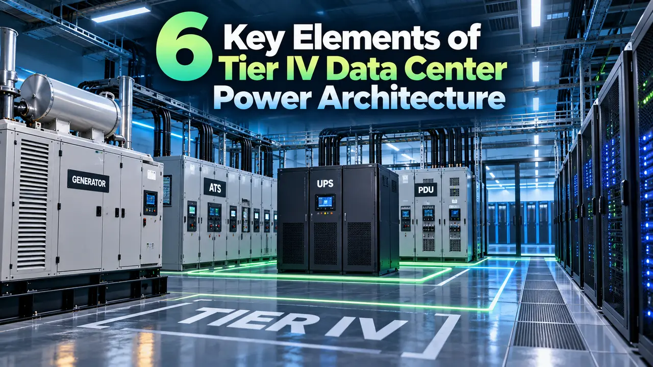
Tier IV Data Center Power Architecture
A data center classified as Tier IV under the Uptime Institute framework is expected to tolerate any single equipment failure without dropping the critical IT load, and the power architecture is what actually delivers that promise.
That framework sits alongside the broader Electrical Regulations and Standards a facility must already meet, since Tier certification adds reliability requirements on top of, not instead of, code compliance.
Getting there means every major component along the power path exists twice, arranged as two electrically separate paths commonly labeled Path A and Path B, each sized to carry the full critical load on its own.
The engineering philosophy is simple to state and demanding to build. Every source, every transformer, every UPS, and every distribution board needs a true independent twin, not just a spare sitting nearby.
Six building blocks make up the complete chain, starting at the utility connection and ending at the server power supply itself, and each one plays a distinct role in keeping the load alive during a fault.
None of the six blocks work in isolation. A weak link at any single stage, even one, quietly turns a fault tolerant design back into an ordinary redundant one on paper only.
Cost is the honest tradeoff behind all of this. Doubling every utility feed, transformer, generator, and UPS system roughly doubles the capital and ongoing maintenance cost compared with a simpler Tier II or Tier III design.
The 6 Building Blocks of Tier IV Power Architecture
Following the six blocks in order shows exactly how a fault at any single point still leaves the load fully powered from the other path.
The objective across all six blocks is the same. A single fault anywhere in the chain should never be able to interrupt the critical IT load, since the other path is always ready to carry the full demand.
Downstream of the switchgear, each path typically feeds its own Motor Control Center (MCC) Explained panel serving pumps, chillers, and air handling equipment that support the IT load rather than power it directly.
Every backup generator in the chain relies on the same rotating machine principle covered in Alternator Working Principle Explained, just scaled and paralleled to match the facility's full critical load.
Tracing the A and B Power Paths
This simplified layout mirrors how a Tier IV facility is normally drawn on its own Single Line Diagram, with Path A and Path B kept visually and electrically separate from the utility feed down to the rack.
Redundancy Levels Behind Tier IV Power Architecture
N and N+1
N is the bare minimum capacity with no spare path. N+1 adds one extra unit, enough to cover a single component failure but not a full path outage.
Tier I to III2N (Fault Tolerant)
Two complete, independently operable systems, each fully rated for the critical load on its own, with no shared point between them.
Tier IVRedundancy and fault tolerance sound similar but are not the same idea, and the difference decides whether a facility can honestly call its design Tier IV.
A poorly executed transfer between Path A and Path B can itself trigger the very Voltage Sag, Swell, and Flicker Explained events a fault tolerant design is supposed to prevent, which is why transfer switch timing gets tested as carefully as the paths themselves.
Redundancy
Extra capacity exists somewhere in the system, but a switch, a shared bus, or a single control point can still create one path to a total outage.
Fault Tolerance
Every path is truly independent end to end, so a fault in electrical separation, physical routing, protection, or control never cascades to the second path.
The real engineering challenge is proving that independence between the two paths, not just installing a second set of equipment and calling the design finished.
Documented failover testing, separate maintenance windows for each path, and a clear commissioning record are what give a facility confidence that its 2N design actually behaves as fault tolerant under real conditions.
Estimating Path Availability
A quick way to see why two independent paths matter so much is to compare the unavailability of a single path against two paths operating together.
Unavailability of Path A = 0.1 percent = 0.001
Two independent paths, both must fail together to drop the load:
Combined unavailability = 0.001 × 0.001 = 0.000001
Combined availability = 99.9999 percent
Result: two independent 99.9 percent paths behave like one path rated near six nines
This simplified calculation assumes true independence between the two paths, which is exactly why physical separation and independent control systems matter as much as the redundant hardware itself.
Tier I Through Tier IV Compared
| Tier | Redundancy | Concurrent Maintainability | Fault Tolerant |
|---|---|---|---|
| Tier I | N | No | No |
| Tier II | N+1 | No | No |
| Tier III | N+1 | Yes | No |
| Tier IV | 2N or 2N+1 | Yes | Yes |
Concurrent maintainability means any single component can be taken offline for maintenance without affecting the load, while fault tolerance goes one step further and covers an unplanned failure as well.
Where This Architecture Is Used
Not every facility needs, or can justify the cost of, a fully fault tolerant power system, so this design shows up mainly where downtime carries a very direct and very large cost.
Telecom carrier hotels and semiconductor fabrication support rooms follow the same reasoning, since a dropped power feed there can halt operations well beyond the building itself.
Common Mistakes When Designing for This Level of Reliability
Shared control system: both UPS paths reporting to one building management platform quietly reintroduces a single point of failure that hardware redundancy alone cannot fix.
Other frequent gaps include routing Path A and Path B cables through the same conduit, relying on a single fuel supplier for both generator systems, and skipping periodic failover testing between the two paths.
Even labeling mistakes cause real problems. A technician who cannot instantly tell Path A cabling from Path B cabling can accidentally isolate both paths during what should have been routine maintenance on just one.
Estimated Annual Downtime Calculator
Reference Document
Watch: Data Center Redundancy, N, N+1, and 2N Explained
Tier IV Data Center Power Architecture FAQs
Related Articles on This Site
- Single Line Diagram Symbols and How to Read One
- Voltage Sag, Swell, and Flicker Explained
- Motor Control Center (MCC) Explained
- Alternator Working Principle Explained
- Electrical Regulations and Standards
External References
What We Learn Today
- Tier IV Data Center Power Architecture runs two fully independent 2N paths from utility to server.
- Fault tolerance is proven through electrical separation, physical routing, and independent control, not just extra hardware.
- Dual corded IT equipment is what finally puts that independence to work at the rack level.