
A safety instrumented system is only as strong as the process used to build it. The SIS safety lifecycle from IEC 61511 is that process, and skipping a stage is exactly how expensive incidents happen.
The SIS safety lifecycle is the complete, verified sequence of stages a Safety Instrumented System must pass through, from the first hazard study to the day it's finally decommissioned.
Every process plant that relies on a safety instrumented system to shut down a reactor, close an emergency valve, or trip a compressor is really relying on a chain of decisions made years earlier. The SIS safety lifecycle in IEC 61511 is what documents and controls that chain, so nothing important gets skipped between the original hazard study and the day the system is finally switched off.
Think of the safety lifecycle less like a checklist and more like a bridge's construction records. An inspector years later needs to trace every beam back to a calculation, a test, and a sign-off. The SIS safety lifecycle does the same job for the sensors, logic solvers, and final elements that stand between your process and a hazardous event.
The 10-Stage SIS Safety Lifecycle Wheel
IEC 61511 groups the safety lifecycle into ten stages, wrapped in a ring of ongoing verification and functional safety management. The wheel below shows how each stage connects to the next.
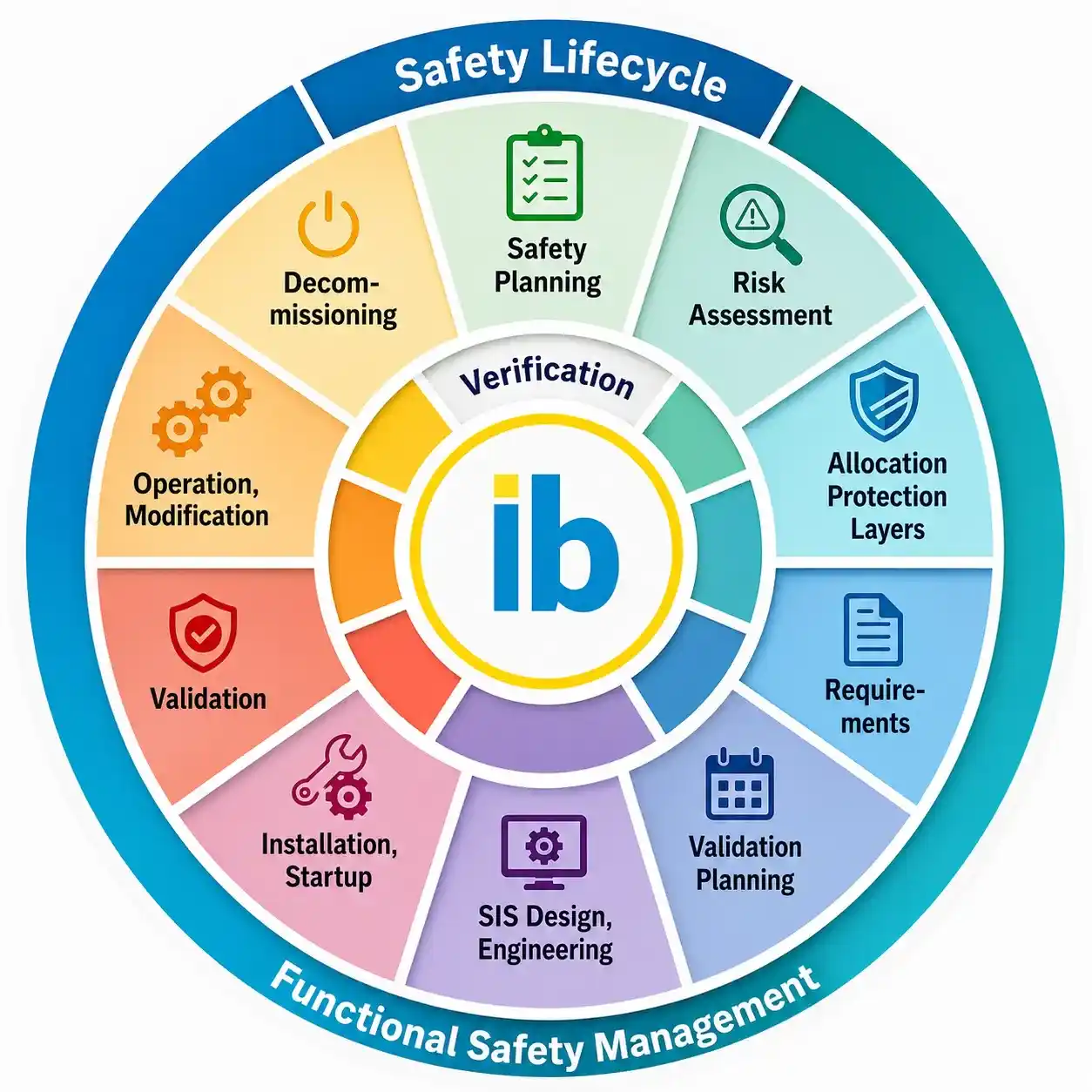
The SIS safety lifecycle wheel: 10 stages wrapped in continuous verification and functional safety management (FSM), based on the IEC 61511 structure.
Three Periods That Group the Safety Lifecycle Stages
It's easier to hold ten stages in your head once you see they fall into three natural groups. Each period has its own owner, its own deliverables, and its own way of failing if it's rushed.
Analysis Period
Covers safety planning, hazard and risk assessment, allocation of protection layers, and writing the safety requirements specification. This is where the required SIL for each safety instrumented function gets set.
Realization Period
Covers validation planning, SIS design and engineering, and installation and startup. Sensors, logic solvers, and final elements are selected, engineered, and physically commissioned in this period.
Operation Period
Covers validation, operation and modification, and decommissioning. This period usually runs the longest and is where proof testing, bypass management, and change control matter most.
What Happens at Each of the 10 Stages
The wheel above shows the shape of the process, but each numbered stage carries its own specific deliverables. Here's what actually happens at each one, in the order a real project moves through them.
Stage 1: Safety Planning
Before any hazard study begins, the project defines who's responsible for which activities, what documentation standards apply, and how the safety lifecycle will be managed across the entire supply chain, from equipment vendors to the end user's own maintenance team.
Stage 2: Hazard and Risk Assessment
Engineers walk through the process design looking for hazardous events, then estimate how likely each one is and how severe the consequences would be. This stage produces the list of scenarios that actually need a safety instrumented function in the first place.
Stage 3: Allocation of Safety Functions to Protection Layers
Not every hazard needs an SIS. This stage decides which layer, a relief valve, an alarm, an operator response, or a safety instrumented function, is responsible for each risk, and sets the target SIL for every safety instrumented function that's needed.
Stage 4: Safety Requirements Specification
The SRS translates the target SIL and the process's safe state into a document detailed enough that a design engineer, who may never have seen the plant, can build the right system from it. A weak SRS is one of the most common root causes of SIS failures years later.
Stage 5: Validation Planning
Before the SIS is even designed, the team decides exactly how it will later prove the finished system meets the SRS. Writing this plan early keeps validation objective rather than becoming a rushed afterthought once installation is already running late.
Stage 6: SIS Design and Engineering
Sensors, logic solvers, and final elements are selected, architectures are chosen, and PFDavg is calculated for every safety instrumented function to confirm the design will actually meet its target SIL once it's built and proof tested on the intervals planned.
Stage 7: Installation, Commissioning and Startup
The designed system is physically installed, wired, and commissioned in the field. Startup procedures confirm the SIS is functioning correctly and safely before the process it protects is allowed to run at full rate.
Stage 8: SIS Validation
Every safety instrumented function is tested against the validation plan written back in stage 5, confirming the system as built genuinely performs the way the safety requirements specification demanded, not just the way the design intended.
Stage 9: Operation and Modification
This is usually the longest stage by far. Proof testing, bypass management, spare parts, incident investigation, and management of change all happen here, and it's where most of the day-to-day functional safety management workload actually lives.
Stage 10: Decommissioning
When a safety instrumented function is finally retired, whether because the process is shutting down or the hazard no longer exists, this stage formally documents that retirement so nobody later assumes protection is still in place when it isn't.
Why Verification Runs Through Every Safety Lifecycle Stage
Verification isn't stage 11 tacked onto the end. It sits inside every single stage of the SIS safety lifecycle, and it means one simple thing: whoever completes a piece of work is not the person who checks it.
Verification is not just re-checking the PFDavg math. Every stage of the safety lifecycle needs its own independent verification step before the next stage begins.
PFDavg, RRF, and How SIL Gets Assigned
Two numbers decide which Safety Integrity Level a safety instrumented function actually achieves: the average Probability of Failure on Demand (PFDavg) and the Risk Reduction Factor (RRF) it produces. They're mirror images of the same thing.
SIL Determination Table: PFDavg and RRF Ranges
Table 3 of IEC 61511-1 ties each Safety Integrity Level to a PFDavg band for low demand mode safety instrumented functions. Use this table alongside the calculator below to sanity-check any SIL determination.
| Safety Integrity Level | PFDavg Range | Risk Reduction Factor | Typical Demand Mode |
|---|---|---|---|
| SIL 1 | ≥10-2 to <10-1 | 10 to 100 | Low demand |
| SIL 2 | ≥10-3 to <10-2 | 100 to 1,000 | Low demand |
| SIL 3 | ≥10-4 to <10-3 | 1,000 to 10,000 | Low demand |
| SIL 4 | ≥10-5 to <10-4 | 10,000 to 100,000 | Low demand, rare in process industry |
Live SIL Calculator: PFDavg to Risk Reduction Factor
Enter the PFDavg for a safety instrumented function and this calculator returns the risk reduction factor and the SIL band it falls into, using the same Table 3 ranges shown above.
The 5 Functional Safety Assessment Checkpoints (FSA-1 to FSA-5)
IEC 61511 recommends five points in the safety lifecycle where a competent person, someone not involved in the work being reviewed, formally assesses whether the safety lifecycle is being followed correctly.
Where the SIS Safety Lifecycle Gets Used Across Industries
Oil and Gas
High integrity pressure protection and emergency shutdown systems on wellheads and pipelines.
Chemical Plants
Reactor trip systems and interlocks that prevent runaway reactions.
Power Generation
Turbine overspeed protection and boiler safety interlocks.
Pharmaceutical
Batch process interlocks protecting against contamination and pressure excursions.
Food and Beverage
Steam and pressure vessel safety systems in processing lines.
Water and Wastewater
Chlorine dosing and pump station safety interlocks.
Do's and Don'ts of Following the SIS Safety Lifecycle
✔ Do
- Document every safety lifecycle stage before moving to the next one
- Use an independent reviewer for verification at every stage
- Recalculate PFDavg whenever field devices or proof test intervals change
- Schedule FSA-4 at planned intervals during operation, not just once
✘ Don't
- Skip the safety requirements specification to save time on design
- Let the design engineer also sign off their own verification
- Leave bypasses in place longer than the documented maintenance window
- Treat decommissioning as an afterthought with no formal stage
Real Whitepapers on SIL and the Safety Lifecycle
FAQs on the SIS Safety Lifecycle
External References
- Safety Lifecycle of IEC 61511, eFunctionalSafety
- IEC 61511 Safety Life Cycle: All 8 Phases Explained, Abhisam
- Safety Integrity Level (SIL) Technical White Paper, Emerson
- Applying the Latest Standard for Functional Safety, IChemE
- IEC 61511 Functional Safety Life Cycle: The Complete Guide to SIS, YouTube
What we learn today
- The SIS safety lifecycle organizes 10 stages into an analysis period, a realization period, and an operation period, all under continuous verification.
- PFDavg and RRF are mirror images of each other: RRF = 1 / PFDavg, and both feed directly into SIL determination per IEC 61511-1 Table 3.
- Functional safety assessment happens at five defined checkpoints, from FSA-1 right after hazard analysis through FSA-5 after major modifications.
- Verification means an independent person checks every stage, not just the final PFDavg number, since early mistakes can undermine everything built afterward.
- Decommissioning is a real stage of the safety lifecycle, not an afterthought, since an SIS left in place unmanaged can create a false sense of protection.