
A pressure transmitter that is correctly specified can still deliver an unreliable reading if it was installed without thinking through connection location, impulse tubing, sensor isolation, and temperature effects together.
There are a genuine number of points to consider in any pressure measurement application, and every one of them deserves real thought during both planning and execution.
Process connections, isolation valves, impulse tubing routing, sensor construction, temperature compensation, remote diaphragm seals, and flange selection all interact with each other. Getting one wrong can quietly undermine an otherwise well specified pressure transmitter installation.
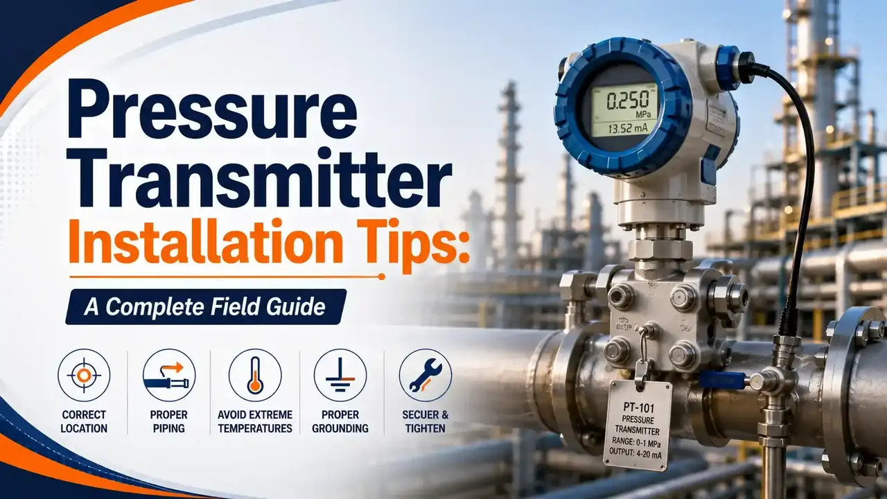
This guide covers every one of these installation factors in detail, including the exact temperature ratings behind common flange choices, the Wheatstone bridge concept behind temperature compensation, and a live tool to help pick the right flange for your process conditions.
Process Connections and Isolation Valves
Process connections should sit on top of the line for gas service, and on the side of the line for other fluids. This single placement decision determines whether condensate, sediment, or trapped gas ends up interfering with the measurement from day one.
Isolation valves matter wherever the transmitter may need to come out of service for replacement or calibration, since tapping directly into a live process without one turns routine maintenance into a shutdown event. This is the same access consideration that applies broadly across instrumentation and control standards for field devices generally.
Impulse Tubing: Self Draining and Self Venting
Keep Impulse Piping Short
Shorter impulse runs mean less opportunity for trapped gas, condensate, or sediment to distort the signal reaching the transmitter.
Slope Gas Lines Toward the Process
Gas service instruments should be self draining, achieved by sloping lines back toward the process to avoid trapping condensables and liquids in the line.
Slope Liquid Lines Toward the Instrument
Liquid and condensable service instruments should be self venting instead, achieved by sloping the lines toward the instrument to avoid trapping gas.
Use Tees Where Solids May Accumulate
Where solids can build up inside the impulse line, tees and plug fittings should replace elbows, allowing the line to be rodded clear without full disassembly.
Test and Drain Valves
Beyond the isolation valve at the process connection, the need for test and drain valves must be evaluated on every application. If the fluid being measured is toxic or corrosive, a blowdown line with its own valve should be provided, tying directly into the broader question of process safety around hazardous fluid handling.
Every valve on the installation must remain accessible from the ground or a suitable platform for maintenance, a detail that matters even more once hazardous area classification restricts how freely technicians can move around the equipment during routine work.
Sensor Construction: Mechanical, Electrical, and Thermal Isolation
Depending on the environment, sensor selection needs to account for physical conditions beyond just the pressure range itself. The sensor may need isolation from the process medium and the external environment on three fronts: mechanical, electrical, and thermal.
Mechanical and thermal isolation come from moving the sensor away from the process flange into the neck of the electronics housing, relieving mechanical stress on the cell and keeping it out of direct heat. This design choice measurably improves static pressure performance.
Glass sealed pressure transport tubes and insulated cell mountings provide the electrical isolation piece, which is conceptually the same principle covered in our guide to galvanic isolation, improving performance and adding transient protection for the electronics inside.

Temperature Effects and Wheatstone Bridge Compensation
High temperatures and large temperature swings both affect pressure measuring equipment in ways that show up as drift rather than an obvious failure. The most common compensation method uses a Wheatstone bridge arrangement, the same balanced resistor network covered in our guide to shunt resistors in instrumentation.
A dummy sensor sits in the bridge alongside the primary sensor. It experiences the same temperature variations but none of the actual process force, so its output cancels the primary sensor's temperature dependent voltage in the bridge arrangement, following the same balance principle behind Ohm's law based circuits generally. Temperature measurement and correction built directly into the device is the alternative, more expensive approach to the same problem.
Remote Diaphragm Seals
Remote diaphragm seals keep the process medium from ever contacting the transmitter's own diaphragm while still measuring process pressure accurately. They are worth considering whenever any of the following apply:
- Corrosion could damage the transmitter or sensing element
- The fluid contains suspended solids or is viscous enough to clog impulse piping
- Process temperature falls outside the transmitter's normal operating range
- The process fluid may freeze or solidify inside the transmitter or piping
- The process medium needs flushing out between batches
- Sanitary or aseptic conditions must be maintained
- Wet leg maintenance needs to be eliminated entirely
- Density or other derived measurements are required
A remote diaphragm seal solves a real contamination or clogging problem, but it introduces a new one of its own: everything downstream of that seal now depends on the fill fluid behaving predictably across the process temperature range.
Watch: How Remote Seal Pressure Transmitters Work
This video covers exactly how a remote seal pressure transmitter isolates the process medium while still delivering an accurate reading.
Video: "How Remote Seal Pressure Transmitter Works", via YouTube.
Selecting Remote Seal Components Correctly
Favor Larger Diaphragm Diameters
Larger diameter diaphragms minimize the temperature effects that are common with remote seal systems.
Keep Capillary Length Short
Minimizing capillary length reduces temperature effects and genuinely improves response time as well.
Match Both Sides in a Two Seal System
The same diaphragm size, capillary length, and fill fluid should be used on both sides of the transmitter in any two seal configuration.
Mount Correctly for Vacuum Applications
Mount the transmitter at or below the lower tap for vacuum service, keeping in mind that capillary length may become a limiting factor.
Choose Fill Fluid for the Extremes
Select fill fluid based on the most extreme process conditions expected, with highest temperature and lowest pressure as the two critical criteria, and confirm compatibility with the process fluid in case of contamination.
Process Flanges: Coplanar, Traditional, and Level
| Flange Type | Typical Characteristics | Max Process Temperature |
|---|---|---|
| Coplanar | Small, lightweight, standard on most newer transmitters, easier to install | Up to 120°C |
| Traditional | Used for biplanar configurations on older or specific installations | Up to 150°C |
| Level | Simple, low cost, permits direct process mounting | Application dependent |
🧮 Interactive Flange Temperature Selector
Enter your maximum expected process temperature to see which flange types can handle it.
Additional Hardware and Impact on the Control Loop
Pulsation Dampeners and Siphons
Pulsation dampener materials and fill fluid must be compatible with the process fluid. Siphons of the correct material are required for vapors above 60°C to prevent condensation issues.
Flushing Connections
If diaphragm seals are specified, the need for a flushing connection must be assessed as part of the same decision, alongside the same transient and electromagnetic interference protection considerations that apply to the transmitter's electronics generally.
Material Build Up
Buildup on the sensing element causes a slower response time in the control loop, degrading process control quality over time.
Overranging
Exceeding a transmitter's rated range causes incorrect readings, and repeated overranging can shorten the sensor's service life.
FAQs on Pressure Transmitter Installation
You May Also Like
Thermocouple and RTD Installation Precautions: A Complete Guide
Pressure transmitters are not the only field instruments where installation quality decides measurement quality. This companion guide covers the same kind of practical precautions for thermocouples and RTDs, immersion length, wiring polarity, and cable routing among them.
Read Full Article →External References
- Differential Pressure Transmitters, Control.com Textbook
- Pressure Measurement, Wikipedia
- Wheatstone Bridge, Wikipedia
What we learn today
- Process connection location, top for gas and side for other fluids, is the first decision that shapes measurement accuracy.
- Impulse tubing must be self draining for gas service and self venting for liquid service, sloped correctly in each direction.
- Sensor construction addresses mechanical, electrical, and thermal isolation separately, each solved with a different design choice.
- A Wheatstone bridge with a dummy sensor is the standard way to cancel out temperature effects in pressure measurement.
- Remote diaphragm seals solve contamination and clogging problems but introduce fill fluid, capillary length, and flange temperature considerations of their own.