
An ordinary diode ignores anything below about 0.6 V, but place it inside an op amp loop and it rectifies millivolts cleanly.
Ordinary diode rectifiers work well for mains voltages but fail on small signals because of their forward drop. An op amp placed around the diode removes that drop and produces an accurate rectified output.

What Is a Precision Rectifier?
A precision rectifier is an op amp circuit that rectifies an AC signal without the forward voltage error of a plain diode, so it can handle signals of only a few millivolts. It is sometimes called a superdiode, and it improves on the diode rectifier circuits used in power supplies.
CircuitDigest explains that the op amp cancels the usual 0.6 V to 0.7 V drop. That makes the circuit suitable for precision measurement and instrumentation.
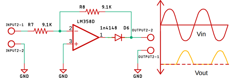
The trick is negative feedback, a core idea from op amp basics. The op amp raises its own output by exactly the diode drop, so the load sees the true input.
The effective threshold becomes the diode drop divided by the open loop gain. With a gain of 100000, a 0.6 V drop shrinks to about 6 µV.
4 Smart Precision Rectifier Circuits
Diode inside a follower loop.
Inverting stage with two diodes that keeps the op amp out of saturation.
Half wave stage plus a summing amplifier.
Uses rail to rail op amps and resistor ratios.
The simple superdiode precision rectifier lets the op amp saturate on negative half cycles. It must then slew back from the rail, which distorts fast signals.
The improved half wave circuit adds a second diode that closes the loop during the other half cycle. The op amp output then only swings about two diode drops.
How the Improved Half Wave Circuit Works
TI covers this arrangement in its Analog Engineer circuit note, with design steps for resistor and diode choice. Low leakage, fast switching diodes give the best results.
Schottky diodes reduce the swing further, as explained in Schottky diode. Check their leakage, which rises with temperature.
Full Wave Absolute Value Circuit
Summer: Vout = minus (Vin + 2 × V1)
Result: Vout = |Vin|
Example, sine input 100 mV peak:
Average of full wave output = 0.637 × 100 = 63.7 mV
RMS of the sine = 0.707 × 100 = 70.7 mV
Meter scaling uses form factor 1.11 to read RMS from the average
CircuitDigest notes that the full wave version adds a summing amplifier so both half cycles are rectified. Resistor matching of 0.1 percent keeps the two halves equal.
Average responding meters use this circuit, then scale by 1.11 to show RMS for sine waves. True RMS converters are explained in RMS value.
Speed and Accuracy Limits
The crossover dead time is roughly the swing divided by slew rate. A 0.5 V per µs op amp needs about 2.4 µs to swing 1.2 V, which matters at 10 kHz and above.
Choose a fast op amp with low offset, or add a small offset trim. For a millivolt precision rectifier, offset is often the biggest error.
Where a Precision Rectifier Helps
An LVDT gives an AC output that must be rectified accurately. Such circuits are part of wider signal conditioning.
Response Calculator
Keep the crossover share below about 1 percent for good accuracy. Choose a faster op amp or lower the frequency if it is higher.
- Rectifies millivolt signals.
- Accurate and linear.
- Works with single or dual supplies.
- Easy to scale with resistors.
- Speed limited by slew rate.
- Offset error at low levels.
- Needs matched resistors.
- More parts than a diode alone.
TI Half Wave Rectifier Circuit PDF
Op Amp Rectifier Video
Precision Rectifier FAQ
Related Articles
- Diode Rectifier Circuits
- Op Amp Basics
- Comparator Circuits Explained
- Voltage Follower Explained
- RMS Value in AC Measurements
External References
- Half Wave Rectifier Circuit, Texas Instruments
- Half and Full Wave Circuits Using Op Amp, CircuitDigest
- Precision Rectifier, Wikipedia
What We Learn Today
- In a precision rectifier, the op amp loop removes the diode drop so millivolts can be rectified.
- The improved half wave and full wave circuits avoid saturation.
- Slew rate, offset and resistor matching set the accuracy.