
A resistive track and a sliding wiper give you an adjustable voltage or resistance with nothing more than a turn of a knob.
A potentiometer is a three terminal variable resistor whose sliding wiper picks off a voltage between two fixed ends. It is one of the simplest ways to set a level, calibrate a circuit or sense position.

What Is the Potentiometer Working Principle?
The potentiometer working principle is simple, a wiper slides along a resistive track and divides the applied voltage in proportion to its position. It is the adjustable form of the voltage divider rule.
The two outer terminals connect to the ends of the track, and the middle terminal connects to the wiper. Moving the wiper changes the resistance on each side of it.
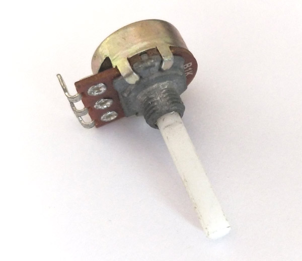
Potentiometers belong to the variable family of resistor types. Common values run from 500 ohms to 1 megohm, with 10k being the most popular.
Tracks are made from carbon, cermet, conductive plastic or wire. Bourns notes that cermet trimmers cover roughly 10 ohms to 5 megohms, while wirewound types offer long life and good conformity.
Potentiometer Working Principle in Divider and Rheostat Modes
In voltage divider mode all three terminals are used, and the wiper voltage follows the wiper position. This mode is used for volume controls, set points and position sensing.
In rheostat mode only one end and the wiper are used, so the part acts as a variable resistor in series with a load. Bourns warns that almost all load current then flows through the wiper contact.
Exceeding the wiper current rating has caused more trimmer failures than any other design error, according to Bourns. Keep wiper current low and use rheostat mode only for small currents.
5 Handy Types of Potentiometers
Trimmers are set during calibration and then left alone, much like the adjustments in a transmitter. Multi turn versions give better setting accuracy than single turn parts.
Digital potentiometers remove mechanical wear completely. They are popular with microcontrollers and in circuits that use analog to digital conversion.
Linear vs Logarithmic Taper
| Feature | Linear Taper | Logarithmic Taper |
|---|---|---|
| Common code | B | A |
| Resistance change | Even along rotation | Slow at start, fast at end |
| At half rotation | About 50 percent | About 10 to 20 percent |
| Typical use | Set points and sensors | Audio volume |
| Reason | Proportional control | Matches human hearing |
Linear taper is the normal choice for instrumentation and control. Log taper suits audio because the ear responds to loudness in a logarithmic way.
Always check the taper code on the part. Using an audio taper for a set point makes adjustment feel uneven and confusing.
Output and Loading Effect Formula
Loaded R2 = (R2 × RL) ÷ (R2 + RL)
R1 = resistance above the wiper
R2 = resistance below the wiper
RL = load resistance on the wiper
Worked example, 10k pot at mid position, Vin = 5 V:
No load: Vout = 5 × 5k ÷ 10k = 2.5 V
With RL = 10k: Loaded R2 = (5k × 10k) ÷ 15k = 3.33k
Vout = 5 × 3.33 ÷ (5 + 3.33)
Loaded Vout = 2.0 V instead of 2.5 V
A load comparable to the pot resistance pulls the output down and makes the response nonlinear. Keep the load at least ten times the pot value, or buffer the wiper.
A voltage follower is the easiest buffer. It presents a very high input resistance, so the potentiometer working principle stays close to ideal.
Where Potentiometers Are Used
Trimmers once handled zero and span adjustments in many analog transmitters. Smart transmitters now do this digitally, but trimmers remain common in simpler equipment.
In bridges, a pot balances the arms for zero output, a technique used in the Wheatstone bridge. The drive speed input on many VFDs also expects a 10k pot.
Selection and Reliability Tips
Check resistance value, taper, power rating and maximum wiper current before selecting. A standard panel pot often handles only about 0.3 W.
Contact resistance variation, called CRV, causes noise as the wiper moves. Conductive plastic tracks give smoother output for position sensing.
Dust and vibration shorten mechanical life. Sealed or digital parts suit harsh industrial panels better.
Understanding the potentiometer working principle also speeds up troubleshooting. A jumpy or noisy reading usually points to a worn track or dirty wiper rather than a failed circuit, and measuring end to end and wiper resistance confirms it quickly.
Loaded Potentiometer Calculator
Increase the load resistance and watch the loaded value approach the unloaded one. That is the whole case for buffering.
- Simple and low cost.
- No power supply needed for the part itself.
- Intuitive manual adjustment.
- Works as divider or rheostat.
- Mechanical wear and wiper noise.
- Loading changes output.
- Limited wiper current.
- Sensitive to dust and vibration.
Bourns Trimmer Primer PDF
How to Wire a Potentiometer Video
Potentiometer Working Principle FAQ
Related Articles
- Voltage Divider Rule Explained
- Resistor Types Explained
- What Is Resistance
- Basics of Ohms Law
- Resistor Color Code Guide
External References
- Trimmer Primer, Bourns
- Potentiometer Pinout and Specs, Components101
- Potentiometer, Wikipedia
- Trimmer, Wikipedia
What We Learn Today
- A wiper divides the track voltage in proportion to its position.
- Divider mode uses three terminals, rheostat mode uses two and loads the wiper.
- Keep the load much larger than the pot value or add a buffer.