
A Parshall flume turns the depth of water in an open channel into a reliable flow rate, with no moving parts and very little head loss. It is the workhorse primary element for effluent, sewage and irrigation flow across India and the world.
Open channels carry effluent, sewage and irrigation water without a full pipe, so ordinary meters cannot be used. A Parshall flume solves this by forcing a known relation between upstream depth and discharge.

What Is a Parshall Flume?
A Parshall flume is a fixed hydraulic structure with a converging inlet, a narrow sloping throat and a diverging outlet, used to measure flow in an open channel from a single depth reading. It belongs to the family of primary elements described in open channel flow measurement.
Ralph Parshall developed the design at Colorado in the 1920s for irrigation canals. Its throat forces the water through critical depth, so the upstream depth alone fixes the discharge under free flow.
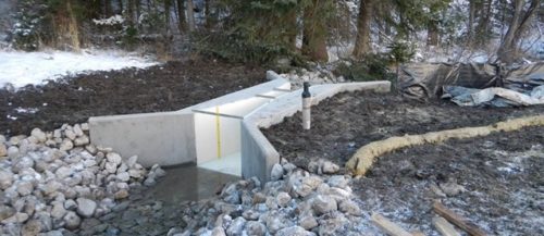
The flume itself is only the primary element. A level sensor reads the head, and a transmitter converts depth to flow, much like a weir or a venturi tube uses a known geometry to relate a simple measurement to flow.
Parts of the Flume and Head Point
The VPC Fiberglass user manual states that the primary free flow point of measurement, Ha, is located two thirds of the converging wall length upstream of the throat. Reading the level anywhere else breaks the calibration that the rating table assumes.
A second point, Hb, sits near the downstream end of the throat and is used only to check or correct for submerged flow. Many small effluent installations never need Hb if the outlet discharges freely.
The USBR Water Measurement Manual lists standard Parshall flume sizes from a 1 inch throat up to a 50 foot throat. Together they cover discharges from about 0.03 to 3000 cubic feet per second.
The Parshall Flume Discharge Equation
Under free flow, discharge follows a simple power law of upstream head, Q = C Ha^n, where C and n depend only on throat width. The exponent sits near 1.5 because flow through a critical section varies with head to the power three halves, a result from Bernoulli equation and continuity.
Q in m³/s, Ha in metres, C and n from the throat table
Example, 1 ft (305 mm) throat Parshall flume:
C = 0.690, n = 1.522, Ha = 0.30 m
0.30^1.522 = 0.16004
Q = 0.690 × 0.16004 = 0.11043 m³/s
Q = 0.1104 m³/s = 397.5 m³/h
Submergence = Hb ÷ Ha = 0.15 ÷ 0.30 = 50.0 percent, below the 70 percent limit, so free flow
| Throat Width | C (SI) | n | Submergence Limit |
|---|---|---|---|
| 3 inch (76 mm) | 0.177 | 1.550 | 50 percent |
| 6 inch (152 mm) | 0.381 | 1.580 | 60 percent |
| 9 inch (229 mm) | 0.535 | 1.530 | 60 percent |
| 1 ft (305 mm) | 0.690 | 1.522 | 70 percent |
| 2 ft (610 mm) | 1.428 | 1.550 | 70 percent |
| 3 ft (914 mm) | 2.184 | 1.566 | 70 percent |
The SI values above are converted from the USBR coefficients for Q in cubic metres per second and Ha in metres. Always confirm the exact constants against the flume maker table or ISO 9826 before configuring a transmitter.
Parshall Flume Flow Calculator
Configure the level transmitter zero at the exact floor elevation of the converging section at the Ha point. A 5 mm zero error at 50 mm head shifts the flow by about 15 percent.
Free Flow vs Submerged Flow
Free flow means the downstream water does not back up enough to affect the throat, so the Parshall flume needs only one head reading. Submerged flow occurs when tailwater rises and Hb divided by Ha exceeds the transition value for that flume size.
These transition limits come from the USBR Water Measurement Manual. Above them, the free flow equation over reads, and a submergence correction from published curves must be subtracted using both Ha and Hb.
- Single head reading at Ha
- Standard rating table applies
- Best accuracy and simplest setup
- Preferred for all new designs
- Needs both Ha and Hb sensors
- Correction curves required
- Accuracy falls as submergence rises
- Unreliable above about 95 percent
If an existing flume floods in monsoon, raise it on a small drop or clear the downstream channel. A raised floor is cheaper than a second sensor and complex correction logic.
6 Smart Steps to Install a Parshall Flume
Steel, concrete and fibreglass flumes are all in use, and fibreglass units are popular because they arrive with the geometry already fixed. Poor concrete casting is a common reason for a site flume that does not match its rating table.
Openchannelflow notes that a Parshall flume can be accurate to within plus or minus 2 percent under laboratory conditions. In the field, approach flow and installation tolerances usually push free flow accuracy to plus or minus 5 percent.
Head Sensors for Flume Flow Metering
Non contact sensor above the Ha point measures echo time to the water surface.
Non contact microwave sensor, less affected by temperature, wind and vapour.
Hydrostatic sensor on the floor at the head point.
Purge tube senses back pressure of the liquid head.
An ultrasonic level transmitter is the usual choice because it never touches sewage. Mount it within the beam angle limits and away from the flume walls, as explained in how an ultrasonic level transmitter works.
Foam, steam and strong sunlight on the sensor face can upset ultrasonic readings, as described in why foam affects level sensors. A radar level transmitter handles such conditions better at a higher price.
For contact sensing, hydrostatic level measurement uses water depth pressure, but silt can bury the sensor. The transmitter then sends flow over a 4 to 20 mA signal to the PLC or data logger.
Parshall Flume Use in Indian Effluent and STP Plants
Effluent treatment plants and sewage treatment plants in India often discharge through open channels to a drain or river. A Parshall flume at the outlet, with an ultrasonic sensor and totaliser, gives the daily volume that pollution control boards ask plants to record.
Pipelines that flow full can instead use an electromagnetic flow meter with suitable lining from liner and electrode selection for wastewater. Partially filled sewers and gravity channels are where flumes remain the practical answer.
Troubleshooting a Flume Flow Reading
- Confirm the sensor sits exactly above the two thirds Ha point.
- Check the transmitter zero against a staff gauge reading.
- Verify C, n and units in the transmitter configuration.
- Look for debris, silt or algae in the converging section.
- Check tailwater height for submergence at high flow.
- Inspect for foam, spider webs or condensation on the sensor face.
- Confirm the converging floor is still level after years of service.
Compare the flume totaliser against a pump run hour estimate or a portable flow meter now and then. Record the result using good practice from measurement uncertainty in calibration, so drift is noticed early.
Second Worked Example: 6 Inch Throat at Low Flow
A small ETP uses a 6 inch throat with C = 0.381 and n = 1.580, and the sensor reads Ha = 0.10 m. Then 0.10^1.580 = 0.02630, so Q = 0.381 × 0.02630 = 0.01002 cubic metres per second, or about 36.1 cubic metres per hour.
A 5 mm zero error at this head would change Q by roughly 8 percent, which shows why careful zeroing matters at low flow. Daily totals feed directly into the plant water balance and flow measurement formulas.
Standards for Flume Measurement
ISO 9826 covers Parshall and SANIIRI flumes, and ASTM D1941 gives the standard test method for open channel flow measurement of water with the Parshall flume. Both specify geometry, head location and the conditions under which the rating applies.
Flumes also compare well with other primary devices described in types of flow meters. Their main advantage over a sharp crested weir is low head loss and self cleaning with solids laden water.
VPC Fiberglass Parshall Flume Manual
Working With Flumes Video
Parshall Flume FAQ
It is a fixed open channel structure with a converging inlet, a sloping throat and a diverging outlet. Water passes through critical depth in the throat, so upstream depth fixes the flow.
A level sensor reads the head at a defined point and a transmitter calculates discharge. It suits effluent, sewage and irrigation channels where pipes do not run full.
Under free flow, discharge is Q = C × Ha^n, where Ha is the upstream head at the measuring point. The constants C and n depend only on the throat width and the units chosen.
For a 1 foot throat in SI units, C is about 0.690 and n is 1.522. With 0.30 m of head, the flow is about 0.110 cubic metres per second.
The head Ha is measured in the converging section at two thirds of the converging wall length upstream of the throat. The zero is the floor level of that converging section.
Measuring at any other place changes the relation between depth and flow. Mount the ultrasonic sensor directly above this point and square to the water surface.
Submerged flow happens when downstream water rises enough to affect the throat. It is judged by the ratio of downstream head Hb to upstream head Ha.
USBR lists limits of 50 to 80 percent depending on throat size. Above the limit, a correction using both heads is needed or the free flow equation over reads.
Openchannelflow quotes about plus or minus 2 percent under laboratory conditions. Field installations usually achieve around plus or minus 5 percent because of approach flow and construction tolerances.
The USBR manual gives plus or minus 3 to 5 percent plus the head sensor error. Careful zeroing and a level converging floor keep the error near the low end.
Ultrasonic level sensors are most common because they are non contact and easy to maintain. Radar sensors work better with foam, vapour, wind and changing air temperature.
Submerged pressure sensors and bubblers suit heavy foam but can foul with silt. Whatever the choice, a good zero at the Ha point matters more than the technology.
ISO 9826 covers the measurement of liquid flow in open channels with Parshall and SANIIRI flumes. ASTM D1941 is the matching American test method for water flow measurement.
Both define the geometry, the head point and the limits of free flow. Manufacturer manuals then give the exact C and n values for each throat size.
Related Articles
- Open Channel Flow Measurement
- Ultrasonic Level Transmitter Working
- Liner and Electrode for Wastewater
- Electromagnetic Flow Meter Working Principle
- Types of Flow Meters
External References
- Parshall Flume User Manual, VPC Fiberglass
- Water Measurement Manual, Chapter 8, Parshall Flumes, USBR
- Parshall Flume, Wikipedia
What We Learn Today
- A Parshall flume forces water through critical depth in its throat, so one upstream head reading at the Ha point gives the open channel flow rate.
- Free flow discharge follows Q = C × Ha^n, and a 1 foot throat with 0.30 m head passes about 0.110 cubic metres per second.
- Submergence limits range from 50 to 80 percent by throat size, and above them both Ha and Hb are needed for a corrected flow.