An NTC thermistor gives a large resistance change for a small temperature change, but the curve is far from a straight line. This guide shows how the beta equation turns that curve into a usable temperature with real datasheet values and a calculator.
The beta equation is the simplest way to convert NTC thermistor resistance into temperature. We work through the formula, the B value, the divider circuit and the accuracy limits with solved numbers.
What Is the NTC Thermistor Beta Equation?
The NTC thermistor beta equation is a two point model that relates thermistor resistance to absolute temperature using one material constant called B or beta. In its common form it reads 1/T = 1/T0 + (1/B) ln(R/R0), where R0 is the resistance at the reference temperature T0, usually 10 kΩ at 25 °C.
- 1/T = 1/T0 + (1/B) × ln(R/R0), with T and T0 in kelvin
- R = R0 × exp[B × (1/T minus 1/T0)] gives resistance from temperature
- B25/85 is calculated from the resistance at 25 °C and at 85 °C
- Common 10 kΩ parts list B values in the range of about 3380 K to 3980 K
- Accuracy is best near the two points used to define B
A negative temperature coefficient thermistor is a ceramic semiconductor whose resistance falls as it warms up, and you can read the basic physics in our guide on NTC and PTC thermistor working. Because the fall is exponential, a 10 kΩ part may read around 33.6 kΩ at 0 °C and only about 700 Ω at 100 °C when B is 3950 K.
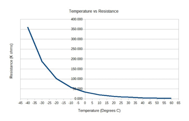
The curve above is the reason a fixed ohms per degree factor never works for a thermistor. The beta equation straightens this curve on a plot of ln(R) against 1/T, which is why it is so popular in firmware and in different temperature sensor comparisons.
NTC Thermistor Beta Equation Formula and Its Two Forms
The beta model comes from the exponential law for semiconductor resistance. Vishay BCcomponents gives the first order approximation R = R25 × exp[B × (1/T minus 1/298.15)] in its NTC application note and states that it is only an approximation.
R = R0 × exp( B × (1/T minus 1/T0) )
Temperature from resistance
1/T = 1/T0 + (1/B) × ln(R/R0)
T in kelvin = °C + 273.15
Both forms of the NTC thermistor beta equation are the same law rearranged, so you can move between resistance and temperature without a lookup table. Always convert to kelvin first, because using degrees Celsius inside 1/T gives a completely wrong answer.
| Symbol | Meaning | Typical value |
|---|---|---|
| R0 | Resistance at reference temperature | 10 kΩ |
| T0 | Reference temperature | 298.15 K (25 °C) |
| B | Material constant between two points | 3380 K to 3980 K |
| R | Measured thermistor resistance | From the divider or meter |
| T | Thermistor body temperature | Result in kelvin |
The B value has units of kelvin because it multiplies a 1/T term. A higher B means a steeper curve and more resistance change per degree, which gives better resolution over a narrower range.
How to Calculate the Beta Value of a Thermistor
Datasheets usually quote B between two named temperatures, written as B25/50, B25/85 or B25/100. Vishay defines B25/85 as ln(R85/R25) divided by (1/358.15 minus 1/298.15), so B25/85 and B25/50 for the same part are slightly different numbers.
R25 = 10000 Ω, R85 = 1070 Ω
ln(1070 ÷ 10000) = minus 2.2349
1/358.15 minus 1/298.15 = minus 0.00056189
B25/85 = 2.2349 ÷ 0.00056189 ≈ 3977 K
This result of about 3977 K matches the class of standard 10 kΩ leaded parts that list R85 near 1.07 kΩ. If you have the full resistance table, compute B for your actual operating band, because a B fitted at 0 to 50 °C will not match one fitted at 25 to 100 °C.
When a datasheet gives several B values, choose the pair that brackets your real process range. A battery pack that runs from 0 to 60 °C is better served by B25/50 than by B25/100.
Thermistor Resistance to Temperature Conversion With an ADC
A microcontroller cannot read resistance directly, so the thermistor sits in a voltage divider with a fixed resistor, as covered in our note on the voltage divider rule. Jameco shows that when the ADC reference and the divider supply are the same voltage, the supply cancels and only the ADC counts are needed.
R_ntc = R_fixed × counts ÷ (ADC max minus counts)
12 bit ADC: ADC max = 4095
Then apply 1/T = 1/T0 + (1/B) ln(R/R0)
Pick the fixed resistor equal to R0 so that the divider sits near mid scale at 25 °C, where resolution is best. For the converter side of the chain, our article on ADC working principle explains how counts relate to the reference voltage.
With a 10 kΩ fixed resistor, R0 of 10 kΩ and B of 3950 K, a reading of 1500 counts gives R = 10000 × 1500 ÷ 2595 = 5780 Ω. The NTC thermistor beta equation then gives about 37.9 °C, a realistic enclosure temperature.
Resolution changes across the range because the curve is steep at cold temperatures and flat at hot ones. If you need the same scaling logic for an industrial input card, compare it with analog signal resolution in PLC systems.
Beta Equation vs Steinhart Hart Equation
The Steinhart Hart equation adds a cubic log term: 1/T = A + B ln(R) + C [ln(R)]³, with three coefficients found from three calibration points. The NTC thermistor beta equation is really the Steinhart Hart form with the cubic term set to zero, so it fits two points exactly and drifts between and beyond them.
| Point | Beta equation | Steinhart Hart |
|---|---|---|
| Constants | One B plus R0, T0 | A, B and C |
| Calibration points | Two | Three |
| Typical error over 0 to 100 °C | Around 0.1 to 1 °C, wider at the ends | Often below 0.02 °C |
| Firmware cost | One log, one divide | One log, one cube |
| Best use | Narrow range, consumer and HVAC | Lab, medical, wide range |
| Data needed | Datasheet B value | R/T table or 3 bath points |
Vishay goes a step further and publishes R = R25 × exp(A + B/T + C/T² + D/T³) polynomials, which it says follow the real curve with an error below 0.1 %. Ametherm offers an online Steinhart Hart calculator that asks for three points at least 10 degrees apart, which is a good rule for your own calibration too.
- Needs only R0, T0 and B from the datasheet
- Very light math for small microcontrollers
- Exact at the two defining temperatures
- Easy to invert in both directions
- B itself changes with temperature
- Error grows outside the defining pair
- Not ideal for wide ranges like minus 40 to 150 °C
- Different B pairs give different answers
For RTDs the same idea of a curve fit appears in the Callendar Van Dusen equation, which plays the role Steinhart Hart plays for thermistors. If you are choosing between sensor families, our thermistor vs thermocouple guide covers range and cost.
The Steinhart Hart equation was published in 1968 by John Steinhart and Stanley Hart for ocean temperature work. Its three term form is still the reference method for precise thermistor calibration today.
Calculator and Solved Example
Enter R0, T0, B and the measured resistance to apply the NTC thermistor beta equation instantly. The default values describe a 10 kΩ, B 3950 part that has dropped to 5 kΩ.
1/T0 = 1 ÷ 298.15 = 0.0033540
ln(5000 ÷ 10000) = minus 0.69315
(1/B) ln(R/R0) = minus 0.69315 ÷ 3950 = minus 0.00017548
1/T = 0.0033540 minus 0.00017548 = 0.0031785
T = 314.61 K = 41.46 °C
The answer makes sense because half the resistance means the part is warmer than 25 °C. For an RTD version of this exercise you can use our RTD resistance to temperature calculator, which applies the platinum curve instead.
Self Heating Error in an NTC Divider
Current through the thermistor makes heat, and the part reads warmer than the medium around it. Vishay defines the dissipation factor in mW/K as the power that raises the body temperature by 1 K, and recommends keeping measuring power below 5 % of that figure to hold self heating under 0.05 °C.
I = 3.3 V ÷ (10 kΩ + 10 kΩ) = 0.165 mA
P = I² × R = 0.272 mW
Assumed dissipation factor = 1.5 mW/K
ΔT = 0.272 ÷ 1.5 ≈ 0.18 K
That 0.18 K error is small for HVAC but large for a medical probe, so precision designs use a higher fixed resistor or power the divider only during the reading. The same problem exists with platinum sensors, as explained in RTD self heating error.
Switch the divider supply from a GPIO pin, wait a few hundred microseconds and take the sample. This cuts average power by the duty ratio and nearly removes self heating from the reading.
Power thermistors used for start current control follow the same law but run hot on purpose, as described in inrush current limiter NTC. For motor windings the protection role usually goes to PTC types instead, covered in motor thermistor protection.
Field Tips and Common Errors
- Confirm R0, T0 and the B pair from the exact part datasheet
- Convert every temperature to kelvin before calculation
- Match the fixed divider resistor to R0 for best mid range resolution
- Check self heating against the dissipation factor
- Use Steinhart Hart if the range is wider than about 50 °C
- Verify one point in an ice bath or calibrated block
Long cables pick up noise, so add a small RC filter at the ADC pin. Other error sources such as immersion depth and lag are covered in temperature measurement errors and temperature sensor response time.
The video above walks through finding beta from two measured points, the same steps we used for B25/85. Compare the result with the NTC thermistor beta equation calculator on this page to check your own work.
NTC Thermistor Beta Equation FAQ
It is the model 1/T = 1/T0 + (1/B) ln(R/R0), which links resistance to absolute temperature using one constant called beta. R0 is the resistance at the reference temperature, normally 25 °C, and T is in kelvin.
The equation comes from the exponential behaviour of semiconductor ceramics. It is exact at the two temperatures used to define B and slightly off between and beyond them.
Measure or read the resistance at two temperatures, convert both temperatures to kelvin, and divide ln(R2/R1) by (1/T2 minus 1/T1). Using 25 °C and 85 °C gives the B25/85 value found on most datasheets.
For a 10 kΩ part reading 1070 Ω at 85 °C, the result is close to 3977 kelvin. Always record which temperature pair you used for the calculation.
There is no single answer, because the B value depends on the ceramic material chosen by the maker. Common 10 kΩ parts are sold with B values such as 3380, 3435, 3950 and 3977 kelvin.
The value printed on the datasheet always names a temperature pair. Check that pair before using the number in firmware, since the same part has a different B25/50 and B25/100.
Yes, because it uses three coefficients instead of one and adds a cubic log term that follows the curvature of the real sensor. Over wide ranges it often stays within a few hundredths of a degree.
The beta equation is simpler and good enough for narrow ranges around room temperature. Many products start with beta and switch to Steinhart Hart when accuracy matters more.
The formula uses 1/T, which only behaves correctly on an absolute scale that starts at zero energy. Using Celsius would make 1/T blow up near 0 °C and give nonsense results.
Add 273.15 to every Celsius value before you calculate, and subtract it at the end. This single step causes most of the mistakes students make with this formula.
Current through the thermistor creates power that warms the part above the medium it is measuring. The error equals the power divided by the dissipation factor of the part.
Vishay recommends using less than 5 % of the dissipation factor as measuring power. Keeping divider current low or pulsing the supply keeps the error near 0.05 °C or lower.
Related Articles
- NTC and PTC Thermistor Working
- Thermistor vs Thermocouple
- RTD Self Heating Error
- Inrush Current Limiter NTC
- Types of Temperature Sensors
External References
- Vishay BCcomponents NTC Thermistors Application Note (PDF)
- Jameco: Temperature Measurement with NTC Thermistors
- Wikipedia: Thermistor
What We Learn Today
- The NTC thermistor beta equation links resistance and kelvin temperature through one constant B, and it is exact only at its two defining points.
- B25/85 is found from ln(R85/R25) divided by the 1/T difference, and a 10 kΩ part reading 1070 Ω gives about 3977 K.
- A voltage divider and ADC give resistance from counts, while Steinhart Hart and low divider current improve accuracy over wider temperature ranges.