
A vendor can only supply the right transmitter or valve if every condition it will face is written down clearly. One standard form, filled in by process and instrument engineers together, turns a tag number into a device that fits the job.
Specification sheets are the contract between the design team, the purchaser and the manufacturer. This guide explains how they are structured, who fills which fields and how to check design margins.
What Is an Instrument Datasheet?
An instrument datasheet is a standard specification form that records the process conditions, functional requirements, construction details and certification needs of one tagged instrument, so that it can be quoted, purchased, inspected and maintained correctly. Each sheet refers to a tag shown on the piping and instrumentation diagram.
The ISA preview of TR20.00.01 explains that each instrument datasheet form lists and provides space for all principal descriptive attributes of a device. This brings uniformity to quoting, purchasing and inspection, and allows electronic data exchange between users and manufacturers.
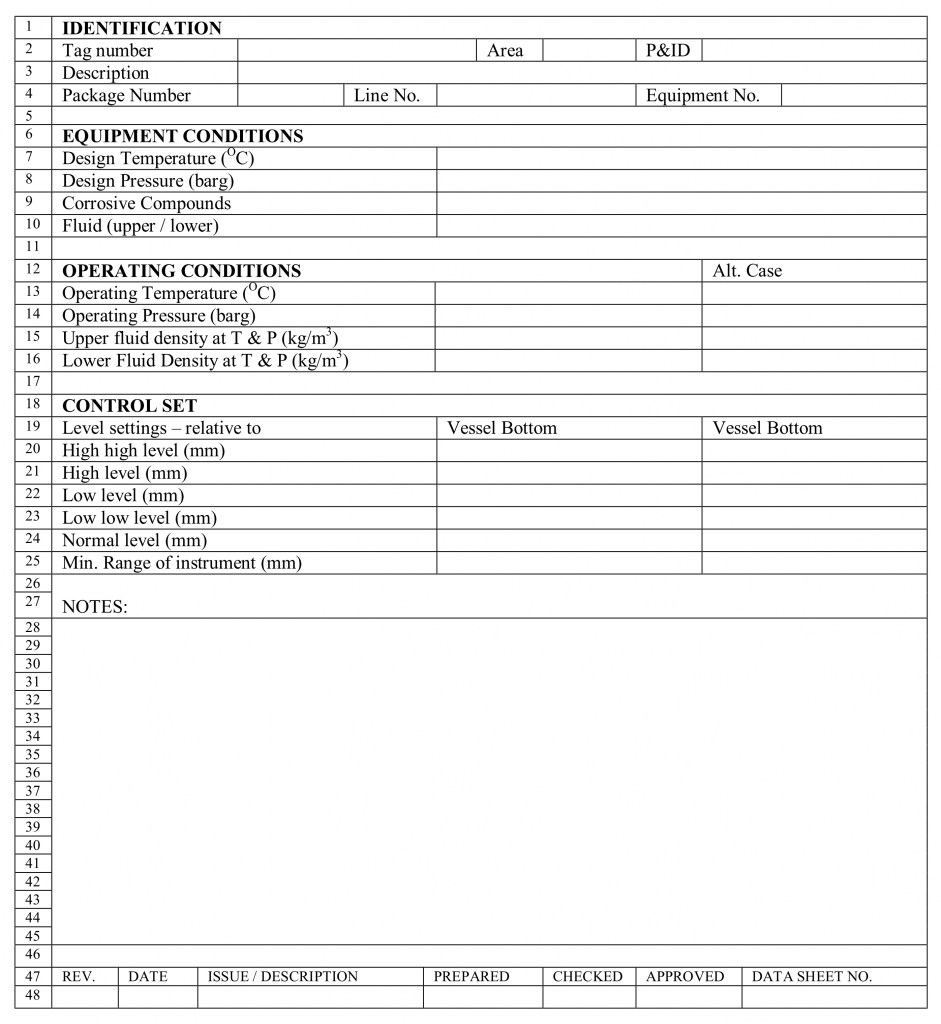
The forms began with ISA S20 in 1981 and were later expanded in ISA TR20.00.01. ANSI lists an edition updated with 27 new forms in 2004 to 2006 and 11 more in 2007.
ISA 20 Forms and Related Standards
| Document | Scope | Use |
|---|---|---|
| ISA S20 | Original specification forms, 1981 | Older projects still reference it |
| ISA TR20.00.01 | Updated forms for most instrument types | Common base for modern projects |
| IEC 61987 | Data structures for process equipment | Digital property lists and catalogues |
| API RP 520 | Relief valve sizing with data forms | Pressure relief devices |
Industrial Monitor Direct notes that API RP 520 contains specification forms for safety and relief valves, which complement the ISA set.
Process Data Versus Mechanical Data
- Fluid name, state and composition.
- Minimum, normal and maximum flow.
- Operating and design pressure.
- Operating and design temperature.
- Density, viscosity and molecular weight.
- Instrument type and range.
- Wetted and body materials.
- Process connection and rating.
- Output signal and power supply.
- Area classification and enclosure.
EnggCyclopedia stresses that the fluids in contact with the instrument must be fully identified, including solids, dissolved gases and corrosive components. Missing one trace component on the instrument datasheet can lead to the wrong wetted material.
Mechanical choices follow the rules in sensor selection criteria. Material certificates are also specified here, see 3.1 and 3.2 material certificates.
7 Essential Parts of Every Datasheet
Area fields must match the hazardous area classification and the temperature class for the location. Enclosure protection is given as an IP rating.
Key Fields by Instrument Type
Range, overpressure limit, diaphragm material, fill fluid and output.
Flow cases, line size, beta ratio or meter size and allowable pressure drop.
Flow cases, Cv, shutoff class, actuator, fail action and noise limit.
Sensor type, insertion length, thermowell data and wake frequency check.
A control valve sheet carries sizing results from control valve sizing, while a flow element sheet carries data from orifice plate sizing. Pressure sensor fields are described in the pressure sensor specifications guide.
Temperature sheets must include the thermowell calculation to ASME PTC 19.3 TW. That check depends on the velocity and density taken from the process section.
Who Fills the Instrument Datasheet
Each instrument datasheet issue carries a revision letter or number, and changed fields are marked with a cloud or triangle. Never let an old revision reach the vendor, because one wrong range can mean a returned instrument.
Design Margin Check Formula
Temperature margin = Design temperature minus Operating temperature
Example:
Operating 8 barg, design 10 barg
Margin = 2 ÷ 8 × 100 = 25.00%
Operating 120 °C, design 150 °C, margin 30.0 °C
25.00% is above a 10% project rule, OK
The required margin comes from your project design basis, not from the instrument datasheet form. Enter that rule and the instrument datasheet values in the calculator below.
Instrument Datasheet Margin Calculator
A negative margin means the instrument may see more than its design value. Correct the process data before issuing the sheet.
- Same layout for every vendor.
- Fewer missed requirements.
- Faster bid comparison.
- Clear change history.
- Only normal case given, no maximum.
- Units mixed between sections.
- Area data copied from another tag.
- Old revision sent for purchase.
ISA TR20 Specification Forms PDF
Datasheet Basics Video
Instrument Datasheet FAQ
It is a standard form that describes the process conditions, construction and certification needs of one tagged instrument. Vendors quote, build and test the device using this single document.
The sheet links to the tag shown on the P&ID for that loop. It stays in the plant records for maintenance, spares planning and later like for like replacement.
ISA S20 first introduced the specification forms in 1981 for process instruments. ISA TR20.00.01 later updated and expanded them to cover most process measurement and control instrument types.
IEC 61987 covers the digital data structures for the same kind of information. Many companies build their own templates on top of these published bases, adding fields for their own needs.
The process engineer fills the fluid properties and all operating and design cases. This data normally comes from the heat and mass balance of the unit.
The instrument engineer should still check the values for sense and consistency. Missing maximum or minimum cases are a very common gap on early issues of the sheet for design review.
The instrument engineer selects the type, range, materials, connections and hazardous area data. The vendor later confirms the exact model code and fills in the vendor section of the form.
Piping and safety teams review the ratings and certification requirements. All their comments must be closed before the sheet is issued for purchase to the shortlisted vendors.
Each change must be tracked so the vendor always works from the latest data. Revision blocks show the date, a short description and the names of the approving engineers.
Changed fields are usually marked with a cloud or a triangle symbol. This simple habit avoids buying a device with a wrong range, material or area certification.
A project sheet states what the buyer needs for the service and site conditions. A vendor sheet describes what the manufacturer actually offers from its standard product range and options.
The final approved sheet merges both views after technical clarification. It then becomes the lasting record for the installed device in the plant for its whole service life.
The margin comes from the project design basis and the applicable piping class. Many projects add a fixed percentage or a minimum pressure above the maximum operating value.
Always use the exact rule given in your client specification. The calculator above only checks the numbers that you enter against that rule, so check the design basis first.
Related Articles
- Piping and Instrumentation Diagram
- Control Valve Sizing Basic Requirements
- Sensor Selection Criteria
- Pressure Sensor Specifications Guide
- Hazardous Area Classification Zones
External References
- ISA TR20.00.01 Specification Forms Preview, ANSI
- Level Instrument Datasheet, EnggCyclopedia
- Datasheet, Wikipedia
What We Learn Today
- An instrument datasheet records process conditions, construction, area data and certification for one tag so vendors can quote and build the correct device.
- Process engineers fill fluid data and operating cases, while instrument engineers select type, range, materials, connections and hazardous area fields.
- ISA 20 style forms bring one layout to every project, and a clear revision block prevents vendors from building to outdated data.