
Every pipe bend already pushes the liquid outward and creates a small pressure difference between its outer and inner walls. Two tappings and a sensitive DP transmitter turn that ordinary bend into a useful flow meter with no extra pressure loss.
A standard long radius elbow can measure liquid flow if you drill two taps at the right angle and read the pressure difference. This guide explains the theory, the formula, real accuracy figures and the field steps that make it work.

What Is an Elbow Flow Meter?
An elbow flow meter is a differential pressure flow element that uses an ordinary pipe bend as the primary device. Two tappings, one on the outer radius and one on the inner radius of the bend, feed a differential pressure transmitter, and the measured difference rises with the square of the flow velocity.
Unlike an orifice plate or a venturi, nothing is inserted into the pipe, so there is no added obstruction and no extra permanent pressure loss. It belongs to the same family as the devices listed in types of flow elements, but it reuses a fitting that the piping already needs.
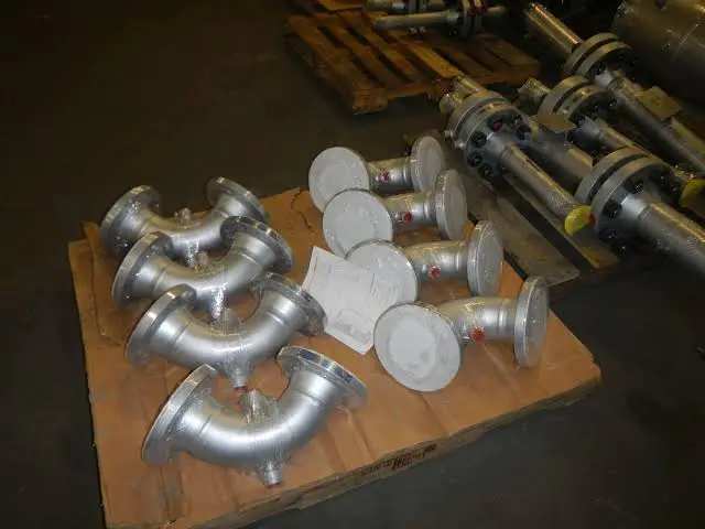
How an Elbow Flow Meter Works
When liquid turns around a bend, every particle needs a centripetal force to follow the curved path. That force comes from a pressure gradient across the pipe, so pressure is higher at the outer wall and lower at the inner wall.
Because the signal follows a square law, the controller must take the square root before using it, exactly as described in square root extraction for DP flow. Doubling the flow multiplies the differential pressure by four.
Thermopedia notes that the main advantage of elbow meters is the absence of any obstruction in the flow. That makes them tolerant of debris that would damage or block an orifice bore.
Elbow Flow Meter Formula and Flow Coefficient
The classic relation treats the elbow like any other head meter, with a geometry term in place of the beta ratio. A flow coefficient C collects everything the simple theory ignores, such as velocity profile and wall roughness.
Flow: Q = V × π D² ÷ 4
R = bend centreline radius, D = pipe inside diameter, ΔP = outer minus inner tap pressure
Example:
D = 100 mm, R = 150 mm (R/D = 1.5), ΔP = 5 kPa, water ρ = 1000 kg/m³, C = 0.98
√(R ÷ 2D) = √0.75 = 0.866 and √(2 × 5000 ÷ 1000) = 3.162
V = 0.98 × 0.866 × 3.162 = 2.68 m/s
Area = 0.007854 m²
Q = 2.68 × 0.007854 × 3600 = 75.88 m³/h
Thermopedia reports that experiments give a coefficient of 1 plus or minus 0.04 for Reynolds numbers above 2 × 10⁵. It also warns that R must be measured within 0.5 percent and D within 0.15 percent, because both enter the equation directly.
The IMEKO paper by Li, Meng and Li studied an elbow with R/D of 1.5 and found that a mismatch between pipe and elbow bore matters too. As the straight pipe diameter changed from 0.947D to 1.05D, the computed coefficient fell from 0.978 to 0.962, a shift of 1.63 percent, which is why pressure tapping geometry and bore matching are treated so carefully in DP metering.
Elbow Flow Meter Calculator
Enter the measured inside diameter, not the nominal size, because schedule changes the bore noticeably. A 4 inch schedule 40 pipe is about 102 mm inside, and that small change shifts the computed flow.
Second Worked Example: Is the Signal Big Enough?
Suppose a 200 mm cooling water line with a 300 mm radius bend carries 150 m³/h. The area is 0.03142 m², so the mean velocity is 0.0417 ÷ 0.03142 = 1.33 m/s.
Rearranging the formula gives ΔP = (V ÷ C)² × ρ × D ÷ R = (1.33 ÷ 0.98)² × 1000 × 0.667, which is about 1.22 kPa or roughly 125 mm of water column. At one third of that flow the signal falls to about 14 mm, so choose a low range transmitter with good stability at the bottom of its span.
Accuracy: Calibrated vs Uncalibrated
PakTechPoint, summarising ASME Fluid Meters, states that a carefully tapped, measured and located elbow meter has about plus or minus 4 percent error without calibration, against roughly 2 percent for an orifice. It recommends the elbow mainly for non critical duty unless it is calibrated.
Primary Flow Signal, which fabricates purpose built elbow meters, lists plus or minus 4 percent uncalibrated, plus or minus 0.25 percent when calibrated, and repeatability of plus or minus 0.20 percent. Its datasheet asks for a pipe Reynolds number above 50,000, which matches the advice in laminar and turbulent flow meter selection.
The Instituto de Pesquisas Tecnológicas in Brazil tested elbow meters for sewage pumping stations. It found the K coefficients constant within 1 percent above a Reynolds number of 10⁵ and reported flow uncertainty better than 2 percent.
Elbow Geometry and Tap Location
Standard R/D of 1.5 gives a stable, predictable signal.
R/D near 1 gives a larger DP but less predictable flow.
Machined bend with factory taps and calibration data.
Field drilled taps on a bend already in the line.
ASME based guidance quoted by PakTechPoint places both taps at 45° from the elbow inlet, in the plane of the elbow centreline, with burr free holes. It also asks for a long radius elbow with R/D above 1.5 and a minimum size of 1½ NPS.
If the plane of the elbow is vertical, the taps sit at different heights and a static head term enters the reading. Either correct it in the calculation or zero the transmitter with the line full and still, as shown in DP flow transmitter calibration.
7 Smart Steps to Install an Elbow Flow Meter
Impulse line practice is the same as for any DP element, so follow the slopes and venting advice in pressure sensing lines. A valve manifold lets technicians equalise and zero the transmitter without draining the line.
Do the field verification with a clamp on ultrasonic meter on the same line before you trust the elbow in the DCS. A simple two point check at low and high flow will reveal a wrong R, D or coefficient quickly.
Comparing the Elbow With Other DP Meters
| Feature | Elbow Meter | Orifice Plate | Venturi Tube |
|---|---|---|---|
| Extra pressure loss | None | High | Low |
| Uncalibrated accuracy | About ±4 % | About ±2 % | About ±1 % |
| Signal size | Small | Large | Medium |
| Solids tolerance | Good | Poor | Good |
| Installation cost | Lowest | Low | High |
For a closer look at the two classic obstruction devices, see orifice plate vs venturi tube. Where an insertion probe is acceptable, an averaging pitot tube gives a larger signal with very low loss.
- No added permanent pressure loss.
- Very low cost when an elbow already exists.
- No moving parts and nothing to wear.
- Handles dirty water and slurry better than an orifice.
- Works in either flow direction with suitable calibration.
- Small DP signal needs a sensitive transmitter.
- About ±4 percent uncertainty without calibration.
- Long upstream straight run is recommended.
- Coefficient depends on exact geometry.
- Gas service is rarely practical.
Where Engineers Use Elbow Meters
An elbow flow meter is a good fit when the duty is liquid, the Reynolds number is high and the purpose is monitoring rather than custody transfer. For billing or tight control, compare it against the options in types of flow meters before deciding.
Troubleshooting Elbow Meter Readings
- Confirm D and R used in the configuration match the real bend.
- Check that both taps are clean, burr free and at 45°.
- Vent air from impulse lines in liquid service.
- Verify zero with the manifold equalised and line full.
- Look for upstream valves or pumps closer than 25D.
- Confirm square root is applied only once, in transmitter or DCS.
- Compare against a clamp on meter at two flow rates.
In the IMEKO experiment, a straight pipe only 5.3 percent smaller than the elbow bore reduced local wall pressure at the bend by more than 20 percent. Matching the upstream pipe bore to the elbow is therefore essential.
Calibration and Standards Practice
ASME Fluid Meters gives the classic elbow guidance, and Primary Flow Signal references R W Miller and ISO 5167 2 straight run tables for its fabricated meters. There is no dedicated ISO 5167 part for elbows, so calibration remains the best route to good accuracy.
A flow laboratory calibration fixes the coefficient across the expected Reynolds range, and the result is documented like any other primary element. In the field, the in situ checks described in wet vs dry flow meter calibration can confirm it later.
Fabricated Elbow Meter Datasheet
Elbow Meter Lecture Video
Elbow Flow Meter FAQ
It is a differential pressure meter that uses a pipe bend as the primary element. Taps on the outer and inner radius read the pressure difference created by centrifugal force.
A DP transmitter converts that difference into a flow signal after square root extraction. Nothing is inserted into the pipe, so there is no added obstruction or extra pressure loss.
Liquid moving around a curve needs a force pointing toward the centre of the bend. That force comes from a pressure gradient across the pipe, so pressure builds up on the outer wall.
The difference grows with density and with velocity squared. It also grows as the bend becomes tighter, because a smaller radius forces a sharper turn.
ASME based guidance gives about plus or minus 4 percent for a well installed meter that has not been calibrated in a laboratory. That is roughly twice the uncertainty of a standard orifice plate.
With laboratory calibration, Primary Flow Signal quotes plus or minus 0.25 percent. Its repeatability of plus or minus 0.20 percent suits trending, balancing and control very well.
Drill both taps at 45° from the elbow inlet, one on the outer radius and one on the inner radius. They must lie in the plane of the elbow centreline and be perpendicular to the wall.
Remove every burr from inside the holes before fitting the impulse lines. A rough edge disturbs the local pressure and shifts the reading noticeably.
Classic ASME based guidance asks for about 25 pipe diameters upstream and 5 downstream. Thermopedia gives the same upstream figure of 25 diameters for reliable and repeatable results.
Some fabricated meters claim to need less straight run than this. Follow the maker datasheet and always confirm the result with a simple field check after commissioning.
It can in principle, but the pressure difference produced by gas is usually very small. Most published guidance therefore treats clean or dirty liquids as the practical duty for these meters.
Water, cooling water and dirty liquids are the most common uses. For gas or steam, an orifice, vortex or averaging pitot tube usually gives a stronger signal.
It works without calibration if you accept about 4 percent uncertainty for routine monitoring duty. Calibration is needed when you want accuracy close to an orifice or a venturi.
A laboratory calibration fixes the coefficient across the working range of Reynolds numbers. A clamp on ultrasonic comparison in the field gives a useful and cheap check afterwards.
Related Articles
- Differential Pressure Transmitter Working Principle
- Square Root Extraction in DP Flow
- Orifice Plate vs Venturi Tube
- Averaging Pitot Tube Working Principle
- Mistakes in DP Flow Measurement
External References
- Elbow Flow Meter Datasheet, Primary Flow Signal
- Elbow Taps Flowmeter Design Requirement, PakTechPoint
- Flow Measurement, Wikipedia
What We Learn Today
- An elbow flow meter reads the centrifugal pressure difference between the outer and inner radius of a bend, and that difference rises with velocity squared.
- Flow follows V = C × √(R ÷ 2D) × √(2ΔP ÷ ρ), so the bend radius, true bore and coefficient must all be known accurately.
- Expect about ±4 percent uncalibrated and much better after calibration, with taps at 45° and about 25D of straight pipe upstream.
