
Two ordinary transistors, wired together in a very specific way, can turn a whisper of base current into enough force to drive a motor.
That trick has a real cost, and understanding it is the difference between using a Darlington pair well and fighting it.
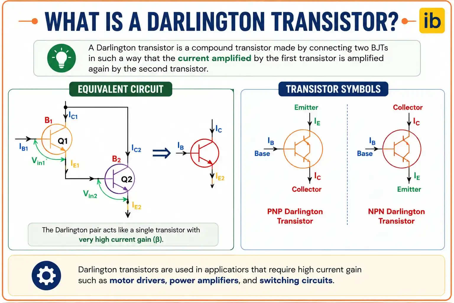
A Darlington pair is two bipolar transistors connected so the first transistor's emitter feeds directly into the second transistor's base, multiplying their individual current gains together into one very high overall gain.
A single transistor can only amplify current so much before you're out of headroom. Stack a second transistor behind it in exactly the right way, and the story changes completely.

Invented by Sidney Darlington at Bell Labs in 1953, this configuration is still one of the simplest ways to turn a tiny control signal into enough current to drive something real.
5 Powerful Facts About How a Darlington Pair Works
These five points cover the wiring, the math, and the real tradeoffs engineers weigh before using one.
Two Transistors, One Combined Behavior
The emitter of the first transistor connects directly to the base of the second, and both collectors join together.
Current Gain Multiplies, Not Adds
Overall gain equals beta1 times beta2, so two ordinary transistors with a gain of 100 each combine into a gain near 10,000.
Very High Input Impedance
Because so little base current is needed, the pair barely loads down whatever circuit is driving it.
Slower Switching and Higher Voltage Drop
Base emitter voltage roughly doubles to about 1.2 to 1.4 volts, and turn off is noticeably slower than a single transistor.
Sold as Ready Made Single Packages
Parts like the TIP120 or the ULN2003A array already contain the pair internally, so no manual wiring is required.
Darlington Pair vs Sziklai Pair
Both configurations multiply gain the same way, but they solve the voltage drop problem very differently.
Darlington Pair
Two transistors of the same polarity, NPN with NPN or PNP with PNP. Base emitter drop is roughly two junctions, about 1.2 to 1.4 volts.
Sziklai Pair
One NPN paired with one PNP transistor. Only one base emitter junction is exposed, so the drop stays near 0.6 to 0.7 volts.
How the Current Amplification Cascades
Picture the process as two amplification stages stacked directly on top of each other.
A microamp level base current can end up controlling a milliamp or even amp level load current. The first transistor never has to work hard, it just has to be enough to wake up the second one.
Interactive Current Gain Formula
Enter each transistor's individual current gain and a base current to see the combined Darlington pair gain and output current calculated live.
Darlington vs Sziklai vs Single Transistor
Here's how the three options stack up on the specs that matter most.
| Parameter | Single Transistor | Darlington Pair | Sziklai Pair |
|---|---|---|---|
| Typical current gain | 50 to 300 | 2,500 to 50,000+ | 2,500 to 50,000+ |
| Base emitter voltage drop | 0.6 to 0.7 V | 1.2 to 1.4 V | 0.6 to 0.7 V |
| Switching speed | Fast | Slower | Faster than Darlington |
| Transistor polarity | Single type | Same polarity pair | Complementary (NPN + PNP) |
Where Darlington Pairs Are Used
Motor Drivers
Driving DC motors directly from a microcontroller pin's tiny current.
Relay and Solenoid Drivers
ULN2003A style arrays switching inductive loads safely.
Audio Amplifiers
High input impedance buffer and output driver stages.
LED and Lamp Switching
Driving displays and lighting from low current logic signals.
Robotics
Interfacing sensors and microcontrollers with higher current actuators.
Power Regulators
Pass transistor stages needing high gain and low base drive.
Do's and Don'ts of Using a Darlington Pair
✓ Do
- Account for the higher base emitter voltage drop when biasing the circuit
- Add a bypass resistor to speed up turn off if switching speed matters
- Use a packaged part like the TIP120 or ULN2003A for simpler, more reliable designs
- Consider a Sziklai pair when a lower, more stable voltage drop is important
✗ Don't
- Use a Darlington pair in circuits needing genuinely fast switching
- Forget that power dissipation rises with the higher saturation voltage
- Assume the datasheet gain figure holds constant across all current levels
- Ignore thermal runaway risk in high power designs without proper biasing
Thermal Runaway: A Real Design Risk
Stacking two high gain stages together creates a feedback loop that needs careful handling in power applications.
As the pair warms up, leakage current rises, which increases collector current further, which generates more heat still. Left unchecked, this cycle can destroy the transistor.
Adding a small emitter resistor or a base bleeder resistor gives leakage current somewhere to go instead of feeding straight into the second transistor's base, keeping the pair thermally stable.
Reference Materials on Darlington Pairs
FAQs on Darlington Pairs
External References
- Darlington Transistor and the Sziklai Darlington Pair, Electronics Tutorials
- Darlington Transistor Pair: Working, Application and Examples, Circuit Digest
- Darlington vs Sziklai Pair, Circuit Cellar
- TIP120/121/122 Darlington Transistor Datasheet, STMicroelectronics
- ULN2003A Darlington Transistor Array Datasheet, Texas Instruments
What we learn today
- A Darlington pair connects two transistors so the first one's emitter feeds the second one's base, combining their gains together.
- Overall current gain equals beta1 multiplied by beta2, easily reaching 10,000 or more from two ordinary transistors.
- The tradeoff is a higher base emitter voltage drop, roughly 1.2 to 1.4 volts, and noticeably slower switching speed.
- A Sziklai pair achieves similar gain using complementary NPN and PNP transistors, keeping the voltage drop near a single transistor's 0.6 to 0.7 volts.
- Packaged devices like the TIP120 and the ULN2003A Darlington array make the configuration easy to use without manual wiring.