A well sized control valve can still hunt, leak or wear out early if it is installed badly. This guide walks through each step from pipe preparation to the first stroke test, using manufacturer manuals as the reference.
Control valve installation decides how long the trim, packing and gaskets will last. Here are the piping, orientation, air supply and commissioning rules that manufacturers actually publish.
What Is Control Valve Installation?
Control valve installation is the set of mechanical, pneumatic and electrical steps that place a control valve in the pipeline so that it throttles accurately, seals properly and can be maintained safely. It covers pipe cleaning, flow direction, straight runs, orientation, supports, bypass and isolation valves, gaskets, bolting, air supply and the final commissioning checks.
- Clean the line and flush with the valve fully open or removed
- Match the flow arrow on the body to the process flow
- Give about 10D straight pipe upstream and 6D downstream where possible
- Mount the actuator vertical above the valve in a horizontal line
- Fit isolation valves, a bypass and a strainer upstream
- Stroke test 0 to 100 % and check for leaks before handover
Before any control valve installation, it helps to know each part you are handling, so read our guide to the basic parts of a control valve. Installation cannot fix a wrong selection, so the decisions in control valve selection and sizing must already be correct.
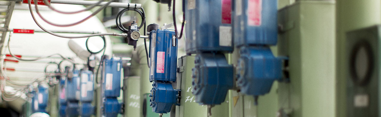
The photo from the Valmet flow control manual shows rotary and globe control valves with actuators and positioners. Every one of them needs the same control valve installation care in piping, support and air supply.
Control Valve Installation Steps
The sequence below follows the installation chapters of the Azbil ACP and ACT manuals, the Fisher easy e manual and the Spirax Sarco guidance. For any control valve installation, your own vendor manual overrides these general rules.
Azbil warns that both pipe flanges must be on the same centre line. Misalignment distorts the body and causes flange leaks, so never pull pipes into line with the valve bolts.
Straight Pipe Requirement for a Control Valve
In control valve installation, disturbed flow from elbows, tees and reducers can reduce capacity and add noise and vibration. The Azbil ACT electric control valve manual asks for straight pipe of at least 10 times the nominal diameter upstream and 6 times downstream, and THINTANK suggests 10 to 20D upstream and 3 to 5D downstream.
Ldown = 6 × D
Solved example, D = 100 mm:
Lup = 1000 mm, Ldown = 600 mm
Face to face 350 mm
Minimum straight section = 1950 mm
Use the face to face length from the valve datasheet, not a guess, because it also sets the flange gap. Where layout makes long runs impossible, discuss the effect on noise and capacity with the vendor, as covered in control valve noise prediction.
Valmet notes in its flow control manual that, as a rule of thumb for liquid piping, the control valve pressure loss at maximum flow is roughly one third of the total dynamic pressure loss in the piping. The installed valve and the pipe system always work together.
Orientation and Flow Direction
Spirax Sarco states that control valves should generally be installed in horizontal pipelines with the spindles vertical, and the actuator normally sits vertically above the valve. The Fisher easy e manual allows any orientation, but warns that positions other than actuator vertical above the valve can cause uneven plug and seat wear and improper operation.
- Even guiding of plug and stem
- Packing wears evenly and seals longer
- Easy access to positioner and gauges
- Condensate drains away from the bonnet
- Side load on stem and guides
- Uneven seat wear and leakage
- Heavy actuators may need their own support
- Water can collect in the yoke or actuator
Always set flow so that it follows the arrow cast on the body, since a reversed globe valve may become unstable or fail to shut off. Check the expected fail action at the same time, using our note on fail open and fail closed valves.
Bypass and Isolation Valves for a Control Valve
The Fisher easy e manual recommends a three valve bypass when the process must keep running during inspection or maintenance. That means one isolation valve upstream, one downstream and a bypass valve around the whole station, plus small drain or vent valves between them.
Full bore block valves on both sides let you remove the valve or repack the gland without draining the whole line.
A throttling valve around the station, normally closed, with a capacity close to the control valve.
Small valves between the block valves to depressurise and drain the trapped section safely.
A pipeline strainer protects seat and plug from dirt and weld debris.
Valve Magazine notes that a bypass valve should have a flow capacity close to the control valve, and it suggests 3/4 or 1 inch drain valves between the block valves. Spirax Sarco adds that bypass leakage in normal operation spoils control, so the bypass must seal tightly when closed.
On steam lines, Spirax Sarco recommends a separator or trapping point upstream of the valve. Condensate held behind a closed valve can cause waterhammer the moment it opens, so a drain matters even more than a strainer there.
Read our article on the difference between a strainer and a filter before choosing mesh size. Show the full station on the P&ID so operators know every valve tag.
Line Flushing, Gaskets and Bolting
Weld spatter and scale are the fastest way to ruin a new seat, so every control valve installation needs flushed lines. Azbil asks for the valve to be fully open during flushing and not to change travel, while many sites go further and fit a spool piece in place of the valve.
- New gaskets rated for fluid, pressure and temperature
- Gaskets centred, not protruding into the bore
- Bolts and nuts to the flange standard, no damaged threads
- Nuts fitted loosely first, then tightened evenly in a diagonal pattern
- Welded flanges allowed to cool before installing
- All bolts rechecked after pressure test
For hot service, Azbil also says to raise valve temperature gradually at about 100 °C per hour and not to operate the valve while it is heating. After the first heat up, retighten gasket joints and check the gland, as described in control valve packing.
Air Supply, Positioner and Accessories
The pneumatic side of control valve installation is often rushed, yet it decides speed and stability. Azbil asks for tubing to be blown out before connection, for the first two threads of each fitting to be left free of sealing tape, and for tube sizes large enough that pressure does not drop during a stroke.
Fit a filter regulator close to the valve and set it to the supply on the datasheet, using our guide to the instrument air filter regulator. Wet air causes sticking relays and corroded actuators, so read about dew point in instrument air as well.
Valve station height matters for maintenance. The EPCland piping notes state that standard control valve stations are placed about 600 mm above grade or the operating platform, so the stem, plug and actuator can be removed without removing the body.
Control Valve Installation Mistakes Table
The table collects the control valve installation errors that most often show up during commissioning. Many of them are listed in the THINTANK installation notes and the Azbil manuals.
| Mistake | Result | Correct practice |
|---|---|---|
| Line not cleaned before install | Seat damage, passing valve | Flush with spool piece or valve fully open |
| Flow arrow reversed | Instability, poor shutoff | Match arrow to process flow |
| Valve stroked during flushing | Debris trapped in trim | Keep valve still and fully open |
| Sealant on female threads | Sealant in body, sticky trim | Apply only on male threads |
| Bolts tightened one side first | Gasket leaks, body stress | Diagonal or star pattern |
| No pipe supports near valve | Flange leaks, distortion | Support both sides independently |
| Actuator mounted horizontally | Uneven guide and seat wear | Actuator vertical above valve |
| Manual bypass left open | Loss of control | Lock closed and log bypass use |
Commissioning Checks After Installation
Once the control valve installation is mechanically complete and air is connected, run the checks below before handing the loop to operations. Azbil asks for 0 to 100 % dummy signals to confirm travel and for leak checks on body, gland and gaskets after pressurising.
Calibrate the positioner using our valve positioner calibration procedure, and set the switches in the valve limit switch box at the same time. If the valve hunts in auto, our guide to control valve hunting explains how to separate tuning from mechanical causes.
Use the instrument air consumption calculator when many valves share one air header. A valve signature test recorded at commissioning gives a baseline for every future diagnosis.
The Learn Instrumentation Engineering video shows a typical valve station with block valves and a bypass. Compare it with the types grid above and identify each valve before your next site walk.
Control Valve Installation FAQ
Good control valve installation starts when you clean and flush the line, check the flange gap and align the flow arrow with the process flow. Fit new gaskets, tighten bolts evenly in a diagonal pattern and support the pipe on both sides.
Mount the actuator vertical above the valve where possible and connect clean air through a filter regulator. Finish with a full stroke test and leak checks before handover.
The Azbil ACT manual asks for at least 10 pipe diameters of straight run upstream and 6 diameters downstream. Shorter runs can reduce capacity and increase noise and vibration.
Other makers quote similar figures, so always follow the manual for your valve. On a 100 mm line the Azbil rule needs about one metre upstream and 600 mm downstream.
Many valves can be installed in vertical lines or with the actuator at an angle, but it is not ideal. Fisher states that positions other than actuator vertical above the valve may cause uneven plug and seat wear.
If a vertical line is unavoidable, support heavy actuators separately and check the vendor manual. Spirax Sarco recommends horizontal pipelines with vertical spindles as the general rule.
A bypass lets the process keep running while the control valve is removed, repaired or recalibrated. Fisher recommends a three valve bypass with upstream and downstream isolation valves for this reason.
The bypass valve should have a capacity close to the control valve so the operator can throttle it. It must seal tightly in normal operation, because leakage through it spoils control.
Yes, Azbil asks for the valve to be fully open during flushing and for travel to stay unchanged. Stroking the valve while debris is passing can trap weld spatter between plug and seat.
Many plants prefer to remove the valve and fit a spool piece during flushing. This protects the trim completely and avoids any risk to soft seats or packing.
Fit the strainer upstream of the control valve, normally between the upstream isolation valve and the valve itself. Spirax Sarco recommends strainers in most applications because dirt and abrasives damage the trim.
Add a pressure gauge or drain so the strainer can be checked and cleaned. A blocked strainer starves the valve and can look like a sizing problem.
Related Articles
- Control Valve Selection Key Factors
- Control Valve Sizing Basic Requirements
- Valve Positioner Calibration Procedure
- Control Valve Troubleshooting
- Instrument Air Filter Regulator
External References
- Fisher EZ easy e Control Valve Instruction Manual (PDF)
- Spirax Sarco: Installation and Commissioning of Controls
- Control Valve, Wikipedia
What We Learn Today
- Control valve installation begins with clean pipes, a correct flange gap, the flow arrow matched to the process and new gaskets tightened evenly.
- Give about 10 diameters of straight pipe upstream and 6 downstream, and mount the actuator vertical above the valve in horizontal lines wherever possible.
- A three valve bypass, upstream strainer, clean air supply and a full stroke and leak test complete a reliable installation ready for handover.