
Every pneumatic positioner, I to P converter and actuator depends on a small unit that cleans the air and holds the supply steady. Get its filter grade, drain, set pressure and size right and most valve air problems simply disappear.
A filter regulator strips water, rust and dirt from instrument air and reduces header pressure to a steady supply for the valve. This guide explains its parts, selection, sizing, setting and maintenance for field engineers.
What Is an Air Filter Regulator?
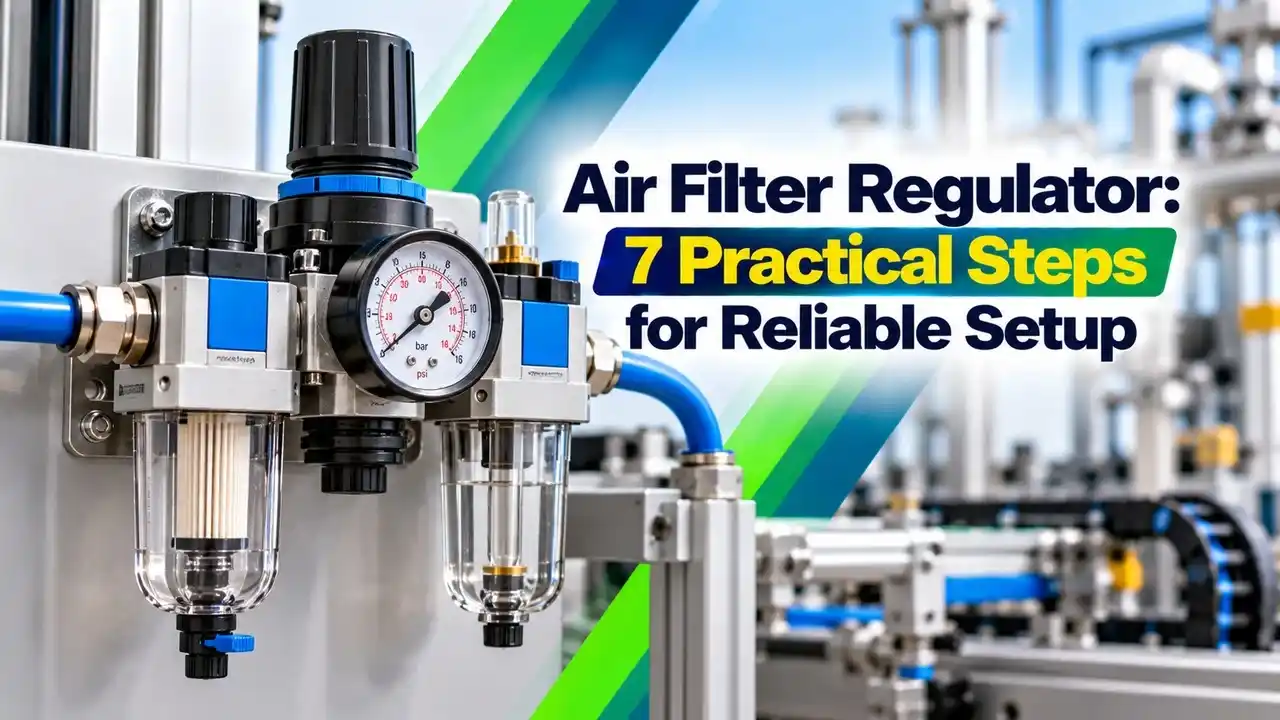
An air filter regulator is a compact pneumatic unit that combines a filter and a pressure reducing regulator in one body, installed on the air supply to each instrument. It removes particles and liquid water from the plant instrument air and holds a steady outlet pressure for a control valve positioner, an I to P converter or a pneumatic actuator.
Plant headers usually run at 5 to 7 bar gauge, while most positioners and converters need a lower and very stable supply. The unit sits on the valve yoke or on a stand close to the instrument, with its gauge showing the outlet pressure.
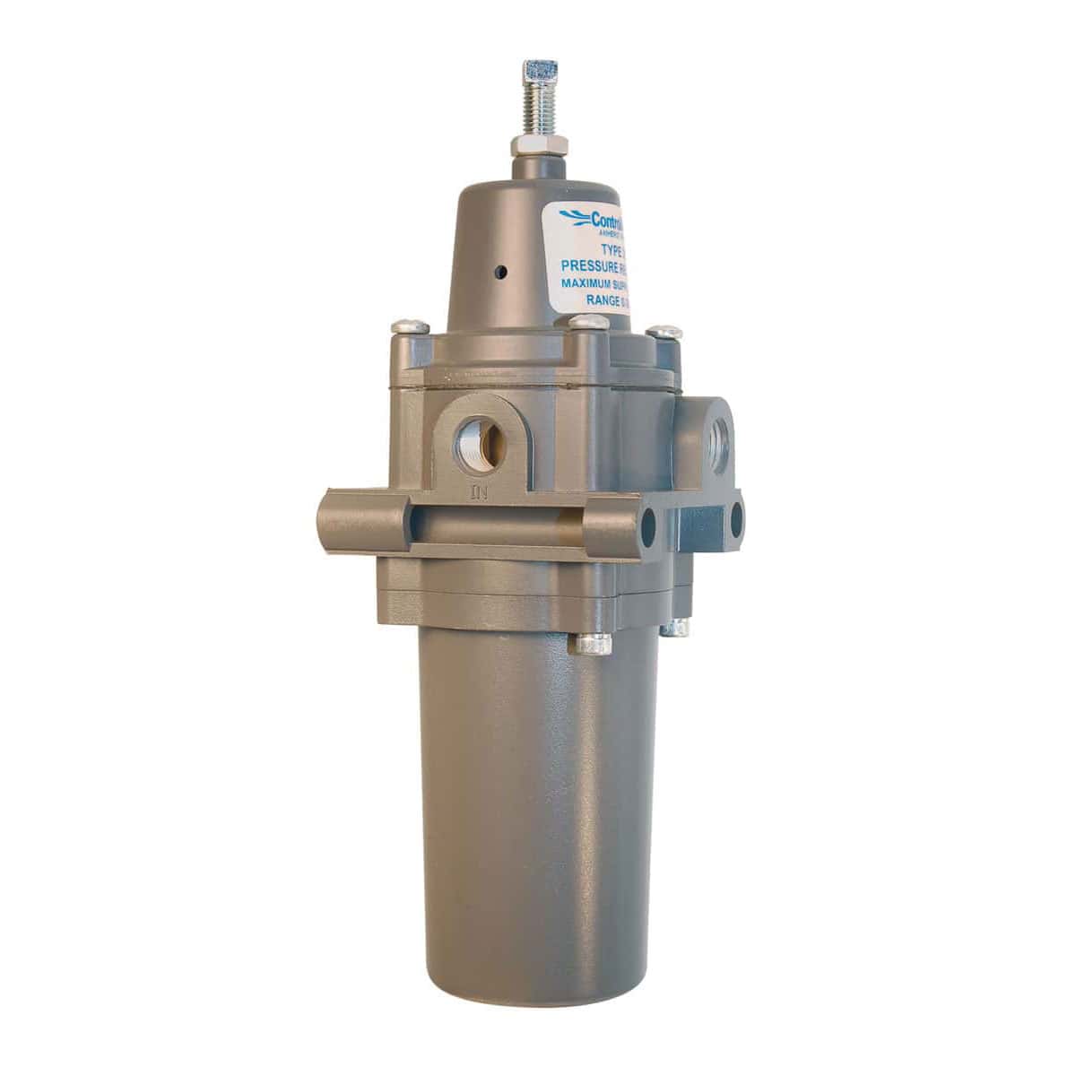
Even dry air from a good plant system carries some rust, pipe scale and occasional water after a dryer upset. Moisture problems in headers are covered in water vapour in instrument air lines, and the local filter is the last line of defence.
Inside the Unit: Filter Bowl, Diaphragm and Relief Seat
Inlet air swirls through deflector vanes, water and heavy dirt are thrown to the bowl, then air passes a sintered or fibre element.
A spring loaded diaphragm opens or closes a valve plug to hold the outlet pressure set by the knob.
A small vent in the diaphragm lets excess outlet pressure escape to air.
Manual petcock or automatic float drain at the bottom of the bowl.
When the outlet pressure falls below the set value, the spring pushes the diaphragm down and opens the valve so more air flows. When the outlet pressure rises, it lifts the diaphragm, closes the valve and, in a relieving unit, vents the excess through the relief seat.
Norgren explains that the filter uses cyclonic action to separate water and debris before the element, and that a measurable pressure drop always occurs through a filter regulator, so correct sizing is essential. The difference between straining and true filtering is explained in strainer and filter difference.
Norgren states that a 40 micron filter removes about 95 percent of the liquid water, and that 40 and 5 micron filters in series approach 99 percent water removal.
Instrument Air Quality and Filter Micron Rating
ISA 7.0.01 sets the familiar instrument air quality limits: a pressure dew point at least 10 °C below the lowest ambient temperature, particles no larger than 40 microns and an oil content of no more than 1 ppm by weight. The local air filter regulator helps keep the air at the instrument within these limits even when the header is not perfect.
ControlAir offers its Type 330 with a 40 micron element as standard and a 5 micron element as an option. Emerson lists 5 micron polyethylene or glass fibre and 40 micron stainless steel elements for its Fisher 67CFR, so a 5 micron grade is the usual choice for smart positioners with small internal nozzles.
The filter cannot fix a wet header, so dew point must still be controlled at the dryer. Read dew point in instrument air to see why freezing and corrosion follow when the dryer fails.
For smart positioners and I to P converters, specify a 5 micron element and an automatic drain on outdoor units. It costs little and avoids most sticky relay and nozzle faults.
Selecting the Right Air Filter Regulator Model
| Parameter | Typical Choice | Why It Matters |
|---|---|---|
| Inlet pressure rating | 250 psig or 17 bar | Header plus safety margin |
| Outlet range | 0 to 35 or 0 to 60 psig | Best resolution near the set point |
| Filter element | 5 micron | Protects positioner nozzles |
| Drain | Auto for outdoor or wet air | No reliance on operator rounds |
| Body material | Aluminium or stainless steel | Corrosive or offshore areas need SS |
| Gauge | Triple scale, 0 to 60 psig | Readable at a glance in bar and kPa |
Choose an outlet range whose top value is not far above the set point, because a regulator set near the bottom of a wide range is harder to adjust finely. For the gauge, apply the usual rules of pressure gauge selection so the normal reading sits in the middle third of the dial.
Emerson lists outlet ranges of 0 to 20, 0 to 35, 0 to 60 and 0 to 125 psig for the 67C series, with a maximum inlet of 250 psig, or 17.2 bar. Gauge readings are always relative to atmosphere, as explained in absolute vs gauge pressure.
Air Filter Regulator Sizing by Cv
An oversized air filter regulator is expensive and an undersized one starves the actuator during fast strokes. Sizing uses the same flow coefficient idea described in control valve flow coefficient, applied to the air path through the filter and regulator.
Q in scfm, ΔP allowed drop in psi, P2 outlet pressure in psia, T in °F, air with SG 1
Example:
Q = 10 scfm, ΔP = 5 psi, outlet = 35 psig so P2 = 49.7 psia, T = 68 °F
ΔP × P2 ÷ (T + 460) = 5 × 49.7 ÷ 528 = 0.4706
√0.4706 = 0.6860
22.48 × 0.6860 = 15.42
Cv = 10 ÷ 15.42 = 0.648
This is a simplified subcritical air formula used by pneumatic suppliers for quick checks. ControlAir lists a Cv of 0.5 for its quarter inch Type 330 and 2.5 for the half inch model, so in this example the larger port size is needed.
Air Filter Regulator Cv Calculator
Peak demand is highest during a full stroke of a large actuator, not during steady control. For fast acting valves, a volume booster or a larger supply line may be needed, and the actuator type matters, as compared in diaphragm vs piston actuator.
7 Practical Steps to Set Up the Supply
Always set the air filter regulator while air is flowing slightly, for example while the positioner is bleeding, because a dead ended regulator reads a little higher than it will in service. Lock the knob after setting so vibration cannot change it.
Second Worked Example: Choosing the Set Pressure
A spring and diaphragm actuator has a bench set of 0.4 to 2.0 bar and a maximum casing rating of 3.5 bar. The positioner needs supply above the top of the bench set to drive the valve fully and to provide seat load, so a setting near 2.5 bar is a reasonable choice.
That leaves margin below the 3.5 bar casing limit even if the regulator creeps up slightly. Always follow the actuator datasheet, because seat load and fail safe action can need a different supply pressure.
Many I to P converters work on a supply of about 1.4 bar, or 20 psi, while the same valve positioner may need 2.5 bar or more. Two units on one valve can therefore have different settings.
Drains, Relief and Safety Points
Manual drains on an air filter regulator need routine opening, and in humid Indian monsoon months they can fill quickly after a dryer trip. ControlAir rates its Type 330 for 250 psig supply with a manual drain but only 150 psig with an automatic drain, so check the drain rating against the header.
The internal relief only vents small excesses, and Emerson states that the 67C relief has low capacity for minor seat leakage only. Where overpressure could damage an actuator, add a proper relief valve, and choose it using types of pressure relief valves.
Air Filter Regulator Maintenance
- Drain the bowl and note any water or oil found.
- Inspect the bowl for cracks and solvent damage.
- Check outlet pressure under flow against the setting.
- Replace the element if pressure drop is high.
- Listen for constant venting at the relief port.
- Verify the gauge reads correctly or replace it.
- Check the auto drain float moves freely.
If valves stroke slowly or positioners drift, check supply pressure at the instrument first, as advised in control valve troubleshooting. A clogged air filter regulator element often shows as normal pressure at rest but a large drop while the valve moves.
Constant hissing from the relief port usually means a damaged seat or diaphragm, or a pressure setting below what downstream devices hold. Where many valves share air, a pneumatic manifold can simplify supply distribution, but each instrument should still have its own regulator.
Keep a few spare elements, diaphragm kits and gauges in the instrument store for each regulator model. Most repairs take less than an hour once the parts are on hand.
- Clean, steady air at each instrument.
- Simple design with low cost.
- Easy local adjustment and visible gauge.
- Protects positioners and I to P converters.
- Cannot fix a wet or oily header.
- Manual drains depend on routine rounds.
- Small relief capacity only.
- Pressure drop rises as the element clogs.
The air system upstream matters just as much, from the compressor type described in single stage and multi stage compressors to the dryer and receiver. A good regulator only finishes the job that the air plant starts.
Fisher 67C Instrument Supply Regulator Bulletin
Filter Pressure Regulator Video
Air Filter Regulator FAQ
It removes particles and liquid water from instrument air and reduces header pressure to a steady supply. It feeds positioners, I to P converters and pneumatic actuators on control valves.
The gauge on the outlet shows the set pressure at a glance. Most units also include a small relief seat that vents excess outlet pressure to atmosphere.
A 5 micron element is the usual choice for smart positioners and I to P converters. General air tools and simple actuators can use 40 micron elements.
Finer elements clog faster, so check the pressure drop during routine rounds. Never remove an element to fix a pressure problem, because dirt will then reach the positioner.
A manual drain is cheap but depends on someone opening it on every round. An automatic float drain empties the bowl whenever enough liquid collects.
Use automatic drains outdoors and wherever the air may carry water or oil. Check the pressure rating, since some auto drain models of an air filter regulator have a lower maximum inlet pressure.
Use the value on the valve or positioner datasheet, often around 1.4 bar for I to P converters and higher for positioners. The supply must exceed the top of the actuator bench set.
It must also stay below the actuator casing rating. Set it while a little air is flowing and lock the knob afterwards.
Estimate the peak air demand during a full valve stroke and decide an acceptable pressure drop. Then calculate the required Cv with a simple gas sizing formula for air.
Choose a model with a rated Cv comfortably above the calculated result. ControlAir lists 0.5 for its quarter inch Type 330 and 2.5 for its half inch model.
Constant venting usually points to a damaged diaphragm, a worn relief seat or dirt on the valve plug. It can also occur when downstream pressure is higher than the setting.
Isolate the unit, depressurise it and inspect the soft parts. A repair kit with a new diaphragm, relief seat and seals usually cures the problem quickly.
Replace it when the pressure drop under flow becomes noticeable, or at the interval set by plant history. Wet or dirty air from a poor header can clog an element within a few months.
Clean, dry headers may allow a yearly change during planned shutdowns. Record the condition each time so the interval can be adjusted with real evidence.
Related Articles
- Control Valve Positioner Working
- Water Vapour in Instrument Air Lines
- Dew Point in Instrument Air Risks
- Control Valve Flow Coefficient
- Pneumatic Manifold Selection
External References
- 67C Series Instrument Supply Regulators Bulletin, Emerson Fisher
- Type 330 Instrument Air Filter Regulator, ControlAir
- Pressure Regulator, Wikipedia
What We Learn Today
- An air filter regulator cleans instrument air and holds a steady supply pressure for positioners, I to P converters and pneumatic actuators on valves.
- Choose a 5 micron element and an automatic drain for smart positioners outdoors, and keep the set point well inside the outlet range.
- Size the unit by Cv for the peak stroke demand, then set pressure above the bench set but below the actuator casing rating.