
This kind of level transmitter has no moving parts, yet it still needs a careful hand at calibration time. Get the LRV, URV, or probe alignment wrong and the transmitter will confidently report a level that simply isn't real.
This measurement approach tracks liquid or solid level by watching the change in capacitance between an insulated probe and the tank wall as the material level rises and falls.
Think of the probe and the tank wall as the two plates of a capacitor. Air alone between them gives one capacitance value. Once liquid starts covering the probe, the liquid itself becomes part of the dielectric between those plates, and since most process liquids have a much higher dielectric constant than air, the capacitance climbs as the level rises.

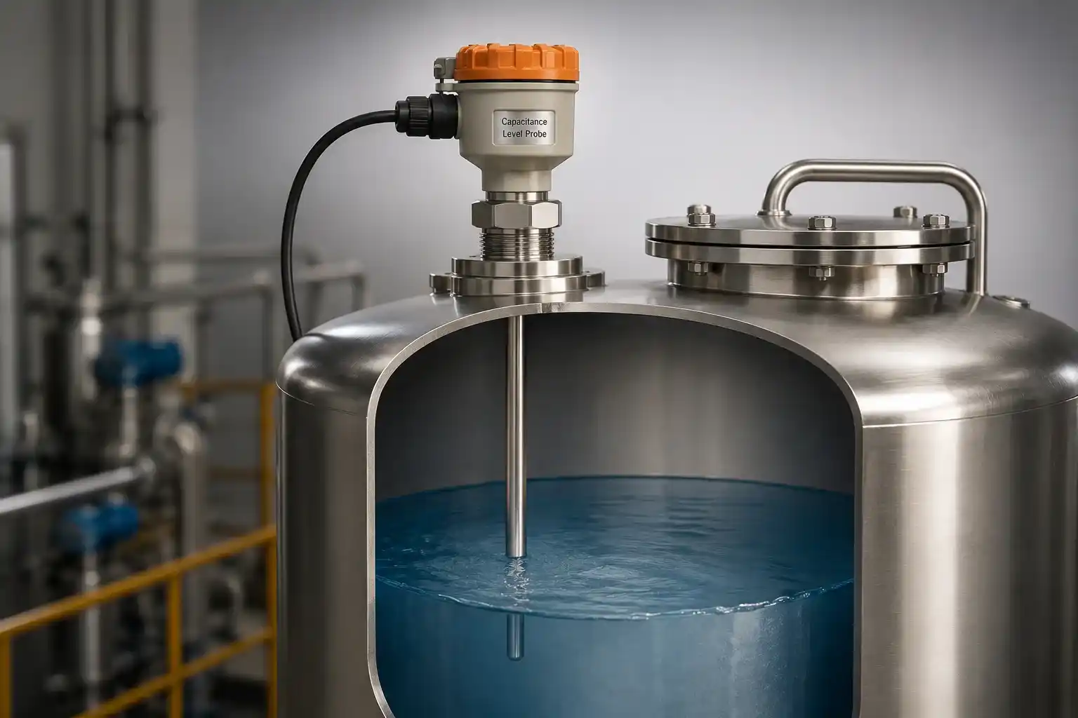
How Capacitance Level Measurement Actually Works
Underneath the probe, the physics is standard capacitor math, just applied to a tank instead of a circuit board.
Capacitance: C = kEA / d
C = capacitance in picofarads
E = permittivity of free space (a constant)
k = dielectric constant of the material between the plates
A = effective area of the plates, d = distance between them
The probe and the tank wall (or a separate reference electrode in a non-metallic vessel) form the two plates. As liquid climbs the probe, it physically replaces air as the dielectric material along more of the probe's length, and since a typical process liquid has a dielectric constant many times higher than air, the capacitance rises accordingly. That capacitance change is what an AC bridge circuit inside the transmitter actually measures and converts into a level reading.
LRV and URV: Setting the Transmitter's Measurement Range
Before any calibration happens, the transmitter needs to know what "empty" and "full" actually mean for this specific tank. That's the job of the Lower Range Value and Upper Range Value.
Both values are measured from the bottom of the probe, and both need to match the datasheet exactly. A transmitter configured with an LRV of 10 inches and a URV of 35 inches, for example, is expected to output 4mA at a 10-inch level and 20mA at 35 inches, with everything in between scaled linearly.
Try It: 4-20mA to Level Percentage Converter
Enter the transmitter's output current to see the corresponding level percentage, exactly what you'd check against a multimeter reading during calibration.
Calibrating a Smart Capacitance Level Transmitter
Smart transmitters lean on a HART communicator to make zero and span adjustments largely automatic, once the physical setup is correct.
Isolate the transmitter from the process tank and bleed off any trapped pressure before touching anything else.
Connect a multimeter to the transmitter, power it with 24VDC, and confirm the status LED behaves as expected.
Verify the zero reading before proceeding. If it isn't clean, release any remaining trapped pressure first.
Connect the HART communicator alongside the multimeter, and set the meter to read mA.
Fill the chamber with water to 0%, then step through 25%, 50%, 75%, and 100% in both directions, recording each reading.
If zero is off, drain to 0% and use the HART communicator's sensor trim, then zero trim option to pull the output to exactly 4mA.
If span is off, fill to 100%, let it settle, then use sensor trim, then span trim to pull the output to exactly 20mA.
Recheck all five points, 0%, 25%, 50%, 75%, and 100%, to confirm the trim actually corrected the error.
Calibrating a Non-Smart Version of This Transmitter
Without a HART communicator to talk to, the same zero and span correction happens by hand, directly on the transmitter's physical adjustment points.
Run through the same setup, fill, and read-back steps used for a smart transmitter.
For zero error, drain fully to 0% and turn the zero screw, pot, or key until the multimeter reads exactly 4mA.
For span error, fill to 100% and turn the span screw, pot, or key until the multimeter reads exactly 20mA.
Recheck 0%, 25%, 50%, 75%, and 100% one more time to confirm both adjustments actually held.
Troubleshooting an Inaccurate Output Reading
An inaccurate reading rarely has just one possible cause, which is exactly why working through this list in order saves time.
| Possible Cause | What To Do |
|---|---|
| Calibration or output current has drifted | Recalibrate the transmitter following the steps above |
| Probe insulation is physically damaged | Contact the vendor, damaged insulation isn't a field repair |
| Probes are no longer parallel to each other | Remove any twist and realign using the spacer |
| Process temperature swings have affected the dielectric | Check actual operating conditions against the transmitter's rating |
| Process connection has worked loose | Tighten the connection, then recalibrate |
| Reference probe connection is loose | Confirm and re-secure all probe connections |
| Transmitter was calibrated incorrectly to begin with | Tighten connections and redo the calibration properly |
| Probe type isn't well suited to this liquid | Confirm probe selection with the manufacturer |
Troubleshooting Fluctuating Output Current
| Possible Cause | What To Do |
|---|---|
| Turbulence in the liquid surface | Install a stilling well around the probe |
| Signal wiring routed too close to noise sources | Reroute wiring away from power cables and contactors |
Installing a Capacitance Type Level Transmitter Correctly
Good calibration can't fix a poorly installed probe, so these details matter before the transmitter ever gets powered up.
Mount the transmitter vertically from the top of the tank.
Choose a location on the tank where turbulence is naturally minimal.
Position the probe so incoming material never flows directly onto it.
Confirm the process connection matches the tank's fitting exactly.
Keep the sensing electrode parallel to the reference electrode or tank wall.
Shield outdoor electronics housings from direct sunlight with a jacket or sunshade.
Flexible probes deserve extra care during installation specifically. Rough handling while feeding a flexible probe into the tank can nick or crack its insulation, and that kind of damage is exactly the "probe insulation damaged" fault that shows up in the troubleshooting table above.
FAQs on Capacitance Type Level Transmitters
What we learn today
- A capacitance level transmitter tracks level by measuring the capacitance change between an insulated probe and the tank wall, C = kEA/d.
- LRV and URV define the transmitter's 4-20mA range and must be set to match the tank's actual dimensions from the datasheet.
- Smart transmitters use a HART communicator's sensor trim function for zero and span correction, while non-smart units rely on physical zero and span adjustment screws.
- Most inaccurate readings trace back to a handful of specific causes: drifted calibration, damaged insulation, misaligned probes, or a loose connection.
- Careful installation, vertical mounting, minimal turbulence, parallel electrodes, and sunlight protection, prevents many of these problems before they start.