Most guided wave radar faults show up clearly on the echo curve once you know where to look. This guide walks through each common symptom, the likely cause and the field fix, with real vendor data and a calculator.
Guided wave radar troubleshooting becomes simple when you read the echo curve and match the symptom to its cause. We cover no echo, wrong level, stuck readings, buildup, low dielectric, foam and interface problems.
What Is Guided Wave Radar Troubleshooting?
Guided wave radar troubleshooting is the process of finding why a GWR level transmitter shows no echo, a wrong level or a stuck value, mainly by reading its echo curve and checking the probe, the configuration and the process. Most faults trace back to a short list of causes such as buildup, low dielectric, the blocking distance, wrong probe length or thresholds set too high or too low.
- Start with the echo curve: check the reference pulse, the surface echo and the end of probe echo
- No echo or lost echo usually means low dielectric, a threshold set too high or a damaged probe
- A level stuck near the top often sits inside the upper blind zone or follows nozzle reflections
- Buildup lowers signal quality and can create a false echo where the deposit sits
- Interface needs a clear dielectric step, typically an upper product below 3 and a lower product above 20
A GWR sends low power pulses down a rod, cable or coaxial probe and times the reflection from the liquid surface. If you are new to the method, first read our article on the guided wave radar level transmitter and how it compares in non contact vs guided wave radar selection.
How to Read a GWR Echo Curve
The echo curve plots signal amplitude against distance from the flange. Every trace shows three key features, and good guided wave radar troubleshooting always begins by finding each one on the screen.
In an Emerson Automation Experts article on Rosemount echo curves, the first check is the reference pulse. A pulse shifted several inches from zero suggests the wrong probe type has been configured, so fix that before touching any threshold.
Emerson also advises setting thresholds as a straight line with control points around fixed obstructions, keeping a buffer of at least 500 mV for temperature changes. The same article warns against the automatic learn function, which can wrap thresholds around transient peaks.
A GWR echo from a surface 3 m below the flange returns in about 20 nanoseconds. The electronics must resolve time differences of picoseconds to reach millimetre accuracy, which is why GWR uses sampling techniques instead of direct timing.
Guided Wave Radar Troubleshooting Symptom Table
Use this guided wave radar troubleshooting table as a first pass in the field. Match the symptom, check the likely causes in order, and confirm each one on the echo curve before you change any setting.
| Symptom | Likely cause | What to check and fix |
|---|---|---|
| No echo or lost echo | Low dielectric, threshold too high, broken probe | Lower threshold, check probe end echo, inspect the probe |
| Level stuck at top | Level inside upper blind zone, nozzle reflection | Move range out of blind zone, trim near zone |
| Level stuck at a fixed value | Buildup or obstruction echo above the surface | Clean probe, check deposits, adjust threshold control points |
| Level reads full on empty tank | Ringing in tall nozzle, false echo near flange | Use a shorter nozzle or a coaxial probe |
| Level offset by a constant | Wrong reference height or probe length | Correct the geometry and verify at a known level |
| Level jumps near bottom | End of probe echo mistaken for surface | Set probe length correctly, use probe end projection |
| Interface missing or unstable | Emulsion layer, small dielectric step | Lower interface threshold, check upper product dielectric |
| Noisy reading | Foam, turbulence, agitator, cable probe swinging | Use damping, anchor the cable, consider a chamber |
Our general level transmitter troubleshooting guide covers the loop side of the problem. Use it alongside this table when the echo curve looks healthy but the DCS still disagrees.
Why Is My Radar Level Transmitter Showing Wrong Level?
A wrong level on a GWR usually means the transmitter has locked onto the wrong echo or is working with the wrong geometry. The quickest check is to compare the reading with a sight glass, dip tape or the level known from a recent tank transfer.
What Is the Dead Zone of Guided Wave Radar?
Each GWR has an upper blind zone near the flange and a lower blind zone near the probe end, where accuracy falls or measurement may not be possible. The Rosemount 5300 data sheet states that in the blind zones the accuracy exceeds ±30 mm and that the 4 and 20 mA points should be set outside them.
When you trim the near zone, Emerson recommends waiting until product is at least four feet below the probe top. Trimming on an empty tank can amplify ambient noise and create new false readings.
Minimum Dielectric Constant for Guided Wave Radar
The surface echo gets weaker as the dielectric constant of the liquid falls. Emerson lists a minimum dielectric of 1.4 for a standard rigid single lead probe and 1.2 for standard coaxial probes on the Rosemount 5300, and these values are guidelines for clean liquids.
| Probe type (Rosemount 5300, Std) | Minimum dielectric | Comment |
|---|---|---|
| Rigid single lead | 1.4 | 1.25 in a metallic bypass or stilling well |
| Coaxial | 1.2 | Best for low dielectric, poor for buildup |
| Large coaxial | 1.2 | Tolerates thin buildup, no bridging |
| Flexible single lead up to 15 m | 1.4 | Rises to 6 for up to 50 m length |
When the dielectric is close to the limit, a chamber or stilling well concentrates the field and helps a lot. Our pages on dielectric constant in level measurement and stilling well level measurement explain why.
End of Probe Shift and Probe Length Settings
The pulse travels more slowly through the liquid than through vapour, by a factor equal to the square root of the dielectric constant. So when product covers part of the probe, the end of probe echo appears further away than the real probe tip.
Level = H minus d
Round trip time t = 2 × d ÷ c
EOP shift = level × (√εr minus 1)
Example: H 5 m, d 3 m, εr 2.25
Level 2 m, t = 20.01 ns
EOP shift = 2 × (1.5 minus 1) = 1.0 m
In this example the probe tip seems to sit at 6 m instead of 5 m. If the probe length entered is wrong, the transmitter may treat the true probe end echo as the surface and report a false level near the bottom.
Guided Wave Radar Troubleshooting Calculator
Enter the reference height, the distance shown on the echo curve and the dielectric constant of the product. This guided wave radar troubleshooting aid gives the level, the echo time and the expected end of probe shift, so you can check if the curve makes sense.
The calculator assumes the probe end sits at the zero level and the vapour space has a dielectric close to 1. For tank volume from that level, use our tank volume from level calculator.
Probe Buildup and Coating
GWR is a contact method, so viscous and sticky liquids can coat the probe. AMETEK explains that paraffin, asphaltenes, hydrates and grit can collect on probes, especially in cold weather or during startups and shutdowns, a topic we also cover in level measurement in high viscosity liquids.
- Tolerate buildup and viscous liquids well
- Easy to clean and inspect
- Long cable versions for tall tanks
- Low cost for most services
- Measure the lowest dielectric liquids
- Ignore nozzles and internals well
- Can bridge with deposits and fail
- Need clean, low viscosity liquids
Foam, Turbulence and Interface Problems
Light dry foam often lets the pulse pass through to the liquid, while dense wet foam can reflect and appear as the surface. Our article on why foam affects level sensors explains how foam density changes the result for every technology.
For interface, the Rosemount 5300 data sheet states that typical applications have an upper product with a dielectric below 3 and a lower product above 20. It can resolve a top layer as thin as 2.5 cm, and the probe must be fully submerged for interface measurement.
Emerson describes an oil and water case where the interface peak amplitude dropped as an emulsion formed, and below about 4000 mV the boundary became unclear. Lowering the interface threshold to about 1000 mV kept the peak tracked, which is a useful lesson for any interface level measurement job.
An emulsion layer has no sharp dielectric step, so the interface echo spreads out and weakens. GWR then reports a point somewhere inside the rag layer rather than a clean boundary.
Step by Step Field Procedure
Follow a fixed guided wave radar troubleshooting order so you do not change two things at once. This sequence works for most brands, including Rosemount, Endress+Hauser, VEGA and Magnetrol.
- Confirm the loop: power, mA output and HART communication are healthy
- Save the echo curve before changing anything
- Verify probe type, probe length and reference height against the data sheet
- Find the reference pulse, surface echo and end of probe echo on the curve
- Check thresholds against the surface amplitude with at least 500 mV margin
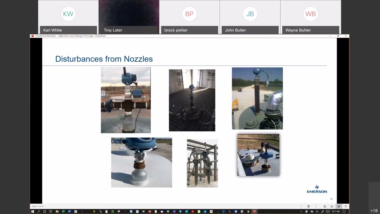
- Look for buildup, nozzle ringing or obstruction echoes near the problem distance
- Save a new echo curve as the baseline after any change
If a cable probe swings in an agitated tank, anchor the weight to the tank bottom or use a centering disc. A moving probe creates noise that no threshold setting can fully remove.
For loop side checks, compare the mA output with the expected value using our 4 to 20 mA signal conversion calculator. To read diagnostics remotely, a basic understanding of the HART protocol is also useful.
Guided Wave Radar Troubleshooting FAQ
A wrong level usually means the transmitter is tracking a false echo or using the wrong reference height or probe length. Buildup, nozzle ringing and the end of probe echo are the most common false targets.
For guided wave radar troubleshooting, save the echo curve and check where the surface peak really sits. Then compare the reading with a sight glass or dip at two different levels.
The dead zone, or blind zone, is the region near the flange and near the probe end where accuracy drops sharply. Emerson states that in these zones the Rosemount 5300 accuracy exceeds 30 mm and readings may fail.
A tall nozzle adds to the upper blind zone. Always set the 4 and 20 mA points outside both zones during configuration.
The minimum depends on the probe type and installation. For the Rosemount 5300, Emerson lists 1.4 for a standard rigid single lead probe and 1.2 for a standard coaxial probe in clean liquids.
Mounting the probe in a metallic chamber or stilling well lowers the usable limit a little. Probe end projection can also help with very low dielectric products like light hydrocarbons.
Yes, guided wave radar can measure the interface between two liquids when their dielectric constants differ clearly. A typical case is oil with a dielectric below 3 floating over water with a dielectric above 20.
The probe must be fully submerged, and emulsion layers weaken the interface echo. Lowering the interface threshold carefully can keep a weak boundary tracked.
First confirm the buildup on the echo curve or with a falling signal quality score, then clean the probe during a planned shutdown. A flushing connection allows cleaning without removing the probe in many installations.
For repeat problems, switch to a single lead or large coaxial probe and insulate the chamber. Coated probes also reduce sticking in waxy service.
Light dry foam often has little effect because the pulse passes through to the liquid surface below. Dense wet foam can reflect enough energy to be read as the surface and give a high level.
Check the echo curve for a broad weak peak above the liquid echo. Antifoam dosing or a chamber away from the inlet often solves the problem.
Related Articles
- Guided Wave Radar Level Transmitter
- Radar Level Transmitter False Echo Handling
- Dielectric Constant in Level Measurement
- Interface Level Measurement
- Level Transmitter Troubleshooting
External References
- Emerson: Rosemount 5300 Level Transmitter Product Data Sheet (PDF)
- Emerson Automation Experts: What GWR Echo Curves Reveal
- Wikipedia: Time domain reflectometer
What We Learn Today
- Guided wave radar troubleshooting starts with the echo curve, where the reference pulse, surface echo and end of probe echo reveal most faults.
- Blind zones, low dielectric liquids, probe buildup and wrong probe length explain most wrong, stuck or lost level readings on GWR transmitters.
- Interface measurement needs a clear dielectric step, and emulsion layers weaken the interface echo, so thresholds must be set with care.