
Every watt a MOSFET or regulator wastes has to travel from a tiny silicon junction to the surrounding air, and each layer on that path adds its own temperature rise. Add those layers correctly and you can pick a heat sink on paper before a single part gets hot.
A heat sink is chosen by working backwards from the hottest junction temperature you will allow. This guide walks through the thermal resistance chain, power loss, interface materials and airflow, with two solved examples and a calculator.
What Is Heat Sink Calculation?
Heat sink calculation is the process of finding the largest sink to ambient thermal resistance, Rθsa, that keeps a semiconductor junction below a chosen temperature at its worst case power and ambient. You subtract the junction to case and case to sink resistances from the total allowed junction to ambient resistance, and the remainder is the heat sink you must buy or beat.
- Allowed total: Rθja = (Tj minus Ta) ÷ P.
- Required sink: Rθsa = Rθja minus Rθjc minus Rθcs.
- Check: Tj = Ta + P × (Rθjc + Rθcs + Rθsa).
- Thermal pads and greases usually add about 0.2 to 2 °C/W between case and sink.
- Design for a junction well below the datasheet maximum, often about 80 percent of it.
The same heat sink calculation works for a MOSFET, a diode bridge, an IGBT module or a linear regulator. Only the power loss formula and the datasheet thermal values change from part to part.
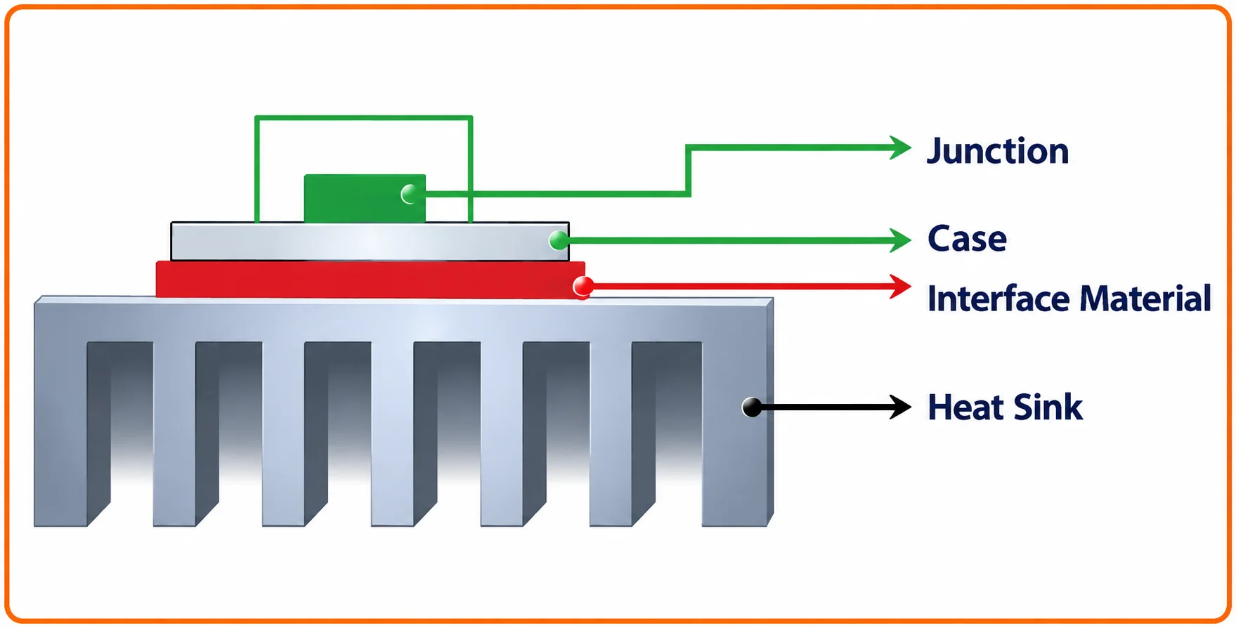
Same Sky (formerly CUI Devices) shows a TO 220 part at 2.78 W reaching an estimated 222 °C junction with no heat sink, using a 62 °C/W junction to ambient rating. With a suitable heat sink and interface pad, its example drops the junction to about 105.7 °C.
Heat Sink Thermal Resistance Formula
Heat flow behaves like current in a series circuit: power in watts is the current, thermal resistance in °C/W is the resistance, and temperature rise is the voltage. Texas Instruments application bulletin SBOA021 writes it as TJ = TA + PD × θJA, with θJA = θJC + θCH + θHA.
Rθsa = Rθja minus Rθjc minus Rθcs
Tj = Ta + P × (Rθjc + Rθcs + Rθsa)
Tj = junction temperature, °C
Ta = worst case ambient near the part, °C
P = power dissipated in the device, W
Rθjc, Rθcs, Rθsa = junction to case, case to sink, sink to ambient, °C/W
Rθjc comes from the device datasheet, Rθcs from the interface material, and Rθsa from the heat sink datasheet or its temperature rise curve. The idea is the same as the series circuits in thermal conductivity problems, just written in electrical form.
Heat Sink Calculation Step 1: Find the Power
For a linear regulator the loss is simply (Vin minus Vout) × Iout, plus a small quiescent term, as explained in linear versus switching regulators. A 12 V to 5 V regulator at 1 A therefore wastes 7 W, more than it delivers to the load.
For a switching MOSFET, add conduction loss I² × RDS(on) to the switching loss. Use RDS(on) at the hot junction temperature, often around 1.5 times the 25 °C value in typical datasheet curves, and take switching loss from the gate charge and edges your gate driver produces.
Always do the heat sink calculation at the highest input voltage, the highest load and the hottest ambient together. A design that is cool on the bench at 25 °C can trip in a 45 °C Indian control panel in May.
Solved Example: Heat Sink Calculation for a MOSFET
Take a MOSFET switching 10 A, with RDS(on) of 30 mΩ at the hot junction and an estimated switching loss of 1 W. Conduction loss is 10² × 0.030 = 3 W, so the total power P is 4 W.
Assume the panel air reaches Ta = 45 °C, the design target is Tj = 125 °C, the datasheet gives Rθjc = 1.0 °C/W, and a silicone pad gives Rθcs = 0.5 °C/W. These are illustrative values, so always use your own datasheet numbers.
Rθsa = 20.0 minus 1.0 minus 0.5 = 18.5 °C/W
Choose a sink rated 12 °C/W at this power:
Tj = 45 + 4 × (1.0 + 0.5 + 12) = 45 + 54 = 99.0 °C
Margin = 125 minus 99.0 = 26.0 °C
Any heat sink with Rθsa at or below 18.5 °C/W meets the target, and the 12 °C/W choice leaves a healthy 26 °C margin. This margin covers dust, ageing of the pad and a slightly hotter enclosure than planned.
Heat Sink Calculator
Second Example: Linear Regulator Heat Sink Calculation
A 12 V to 5 V linear regulator IC in a TO 220 package delivers 1 A, so it dissipates (12 minus 5) × 1 = 7 W. Assume Ta = 40 °C, a target Tj of 125 °C, Rθjc = 3 °C/W from the datasheet and a 0.5 °C/W pad.
The allowed total is (125 minus 40) ÷ 7 = 12.14 °C/W, so the sink must be at most 12.14 minus 3 minus 0.5 = 8.64 °C/W. Adding a 20 percent margin, as Components101 does in its LM317 example, points to a sink near 6.9 °C/W or better.
Notice how a 7 W loss already needs a sizeable finned extrusion. When a heat sink calculation result looks impractical, a switching regulator that cuts the loss is often cheaper than a large heat sink.
Thermal Interface Material and Mounting
No two metal surfaces are perfectly flat, so microscopic air gaps sit between the device tab and the heat sink. Same Sky gives the interface resistance as Rθcs = (thickness ÷ area) × (1 ÷ conductivity), and its example pad on a TO 220 tab works out to about 0.45 °C/W.
Thin layer fills gaps with very low resistance, but needs care and can pump out over time.
Clean, easy and electrically insulating, with somewhat higher resistance.
Softens at operating temperature to flow into gaps like grease.
Classic isolation for TO 220 and TO 247 parts.
Torque the mounting screw to the datasheet value and use an insulating bush when the tab is live. Uneven pressure leaves air gaps that quietly raise Rθcs and spoil the heat sink calculation.
Airflow and Forced Cooling
Natural convection depends on fin orientation, spacing and free air around the sink, so mount fins vertically when you can. In the Components101 worked example, the same channel heat sink falls from about 9.42 °C/W in still air to about 4.8 °C/W at 200 feet per minute of airflow.
That halving shows why airflow belongs in every heat sink calculation, and why a small fan can replace a much larger extrusion. Fan selection, airflow and noise are covered in electronic cooling fans, and the fan itself becomes a part that needs maintenance.
In TI application bulletin SBOA021, the same TO 3 device reaches 145 °C at 100 W on a very good mounting, yet 158 °C at only 10 W on a poor one. Mounting and heat sink choice can matter more than the power level itself.
How to Choose a Heat Sink in 7 Steps
For the final check, a small thermocouple or thermistor on the tab gives the case temperature, and Tj = Tc + P × Rθjc. Sensor choices are compared in types of temperature sensors, and NTC thermistors are easy to glue on.
Heat Sink Calculation Troubleshooting
| Symptom | Likely Cause | Fix |
|---|---|---|
| Part hotter than calculated | Underestimated switching loss or hot RDS(on) | Measure real loss, recalculate at hot values |
| Heat sink cool but part hot | High Rθcs from poor contact or dry paste | Re clean, reapply TIM, torque correctly |
| Fine on bench, trips in panel | Ambient higher inside enclosure | Use panel air temperature, add vents or fan |
| Sink hot all over | Rθsa too high for the power | Larger sink or forced air |
| Temperature creeps up over months | Dust on fins or pad ageing | Clean fins, schedule TIM inspection |
Point an IR thermometer only at a painted or taped spot on the heat sink, not bare aluminium. Shiny metal has a low emissivity and reads far colder than it really is.
- Heat sink calculation uses power loss at worst case input, load and temperature.
- Ambient taken inside the enclosure, not room air.
- Rθjc read from the correct package in the datasheet.
- Interface material and torque match the assumed Rθcs.
- Heat sink Rθsa checked at the actual power and airflow.
- Case temperature measured at full load on the prototype.
- Longer component life and fewer field failures.
- Smaller, cheaper heat sinks with known margin.
- Clear choice between natural and forced cooling.
- Easy to document for design reviews.
- Datasheet values are typical, not guaranteed for your layout.
- Ignores heat lost through the PCB and leads.
- Transient and pulsed loads need thermal impedance curves.
- Nearby hot parts raise the local ambient.
Where Heat Sinks Are Used
Large modules such as IGBTs in a power inverter follow exactly this heat sink calculation chain, just with bigger numbers. Small surface mount parts often use the PCB itself as the heat sink, with thermal vias carrying heat to inner and bottom copper.
Diodes are no exception: a Schottky diode carrying several amps can dissipate a few watts and needs the same check. So can SCRs in phase control heaters.
TI Heat Sinking Application Bulletin PDF
Video on Heatsink Design
Heat Sink Calculation FAQ
First find the allowed total resistance, Rθja = (Tj minus Ta) ÷ P, using worst case values. Then subtract the junction to case and case to sink resistances from that total.
The remainder is the largest sink to ambient resistance you can accept. Pick a heat sink at or below that value, ideally with a 20 percent margin for safety.
Rθsa is the sink to ambient thermal resistance in degrees Celsius per watt. It tells you how many degrees the heat sink rises above the air for every watt it carries.
A lower number means a better heat sink for the job. The value changes with airflow, so always read it at the airflow your enclosure really provides.
For a linear regulator use (Vin minus Vout) × Iout at the highest input voltage. For a MOSFET add I² × RDS(on) at hot junction temperature to the switching loss.
Diodes dissipate their forward voltage times average current. Always use the worst combination of input, load and temperature for every heat sink calculation you do.
Yes, because without it tiny air gaps between tab and sink add a lot of resistance. Components101 puts typical interface materials at about 0.2 to 2 degrees per watt.
Use a thin, even layer and correct screw torque. Too much paste is worse than a thin film, since paste conducts heat far worse than the metal itself.
Find the power and multiply it by the junction to ambient rating, often around 62 degrees per watt for a bare TO 220 package. Add the ambient, and compare the result with your target junction limit.
Same Sky shows a 2.78 watt part reaching about 222 degrees with no sink. As a rough guide, a bare TO 220 package handles only a watt or two in warm air.
Forced air can cut sink to ambient resistance roughly in half or better. In the Components101 example the same sink fell from about 9.42 to 4.8 degrees per watt at 200 feet per minute.
Read the airflow curve from the heat sink datasheet for real numbers. Remember that a fan adds noise, dust intake and a part that can fail in service.
Most silicon parts list a maximum of 125 to 175 degrees, but that is an absolute limit, not a target. Components101 designs for about 80 percent of the maximum to extend life.
Lower junction temperature slows wear mechanisms such as bond wire fatigue. A common practical target is 100 to 125 degrees at the hottest ambient you expect.
Related Articles
- Thermal Vias for PCB Heat Dissipation
- Electronic Cooling Fans and Thermal Efficiency
- Linear vs Switching Voltage Regulators
- MOSFET Working Principle
- What Is Thermal Conductivity
External References
- Heat Sinking: TO 3 Thermal Model, Texas Instruments SBOA021
- How to Select a Heat Sink, Same Sky
- Heat Sink, Wikipedia
What We Learn Today
- A heat sink calculation starts from Rθja = (Tj minus Ta) ÷ P and subtracts Rθjc and Rθcs to find the largest Rθsa you can accept.
- Power loss must be found at worst case input, load and hot RDS(on), with ambient measured inside the enclosure rather than room air.
- Interface material, mounting torque and airflow can change the junction temperature as much as the heat sink size itself does.
