
A person touching a water pipe and a faulty appliance at the same time can be exposed to a dangerous voltage difference, even when the earthing looks perfect. Good bonding joins all touchable metalwork so that difference stays too small to hurt anyone.
Earthing gives fault current a path, but it does not by itself keep nearby metal parts at the same voltage. Equipotential bonding closes that gap by joining pipes, steelwork and equipment frames with properly sized conductors.
What Is Equipotential Bonding?
Equipotential bonding is the practice of connecting all exposed conductive parts and extraneous conductive parts in an installation with low resistance conductors, so that they rise and fall in voltage together during a fault. It works alongside the earthing arrangement described in TN, TT and IT earthing systems, and it is the main reason touch voltages stay safe while a protective device clears the fault.
An exposed conductive part is the metal body of equipment, such as a motor frame, which becomes live only under fault. An extraneous conductive part is metal outside the installation that can introduce a potential, such as a water pipe, gas line or structural steel.
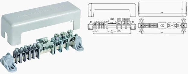
The photo shows an equipotential busbar, where bonding conductors from services and steelwork meet the main earthing terminal. Without it, a fault can leave a pipe at a very different voltage from the frame beside it, a classic cause of electric shock in plant rooms.
Why Bonding Matters Even With Good Earthing
When a phase conductor touches a metal enclosure, fault current flows through the protective conductor and develops a voltage across it. A good earth electrode, sized as shown in earthing resistance calculation, does not remove this voltage, it only sets how much current flows back to the source.
If a nearby water pipe is still at true earth potential, a person holding both the pipe and the enclosure sees the full voltage drop on the protective conductor. Equipotential bonding pulls the pipe up to the same voltage as the frame, so the hand to hand voltage becomes small.
Substation earth grids use the same idea on a larger scale, with a buried mesh acting as equipotential bonding for the whole switchyard. IEEE 80 calls the resulting limits step and touch voltage.
Types of Equipotential Bonding in an Installation
Joins incoming metal services and building steel to the main earthing terminal near their point of entry.
Joins exposed and extraneous parts that can be touched together in one location.
Provides a clean reference for electronics, screens and signal circuits.
Joins metal parts to stop flashover and spark discharge.
Main and supplementary equipotential bonding protect people from shock. Functional bonding for instruments follows the rules in grounding techniques and earthing in process plants, yet all of them meet at one earthing system.
IEC, IS and BS Rules for Equipotential Bonding
| Standard | What It Covers | Key Requirement |
|---|---|---|
| IEC 60364 4 41 | Protection against electric shock | Main bonding in every building, supplementary bonding where disconnection is not fast enough |
| IEC 60364 5 54 | Earthing arrangements and protective conductors | Conductor sizes for main and supplementary bonding |
| IS 732 | Indian code for wiring installations | Follows the IEC 60364 approach for bonding |
| IS 3043 | Indian code of practice for earthing | Earth electrodes, earthing conductors and bonding of metalwork |
| BS 7671 | UK wiring regulations | Clause 544 for bonding sizes and connection points |
| IEC 60079 14 | Electrical installations in hazardous areas | Potential equalisation of all exposed and extraneous parts |
Before you size anything, ask which earthing system the site uses, because the bonding conductor size is linked to the main earthing conductor. A TN C S supply in a city building and a TT supply on a remote pump site lead to different numbers.
Equipotential Bonding Conductor Sizes and Formula
Electrical Engineering Portal, quoting IEC 60364 5 54, gives 6 mm² copper as the minimum main bonding conductor and notes that copper need not exceed 25 mm². The same article lists 2.5 mm² copper for supplementary bonding with mechanical protection and 4 mm² copper without it.
IEC 60364 5 54 also requires the main bonding conductor to be at least half the cross section of the largest protective earthing conductor, with 16 mm² aluminium or 50 mm² steel as alternatives to 6 mm² copper. For the effectiveness of supplementary equipotential bonding, IEC 60364 4 41 gives the resistance check shown below.
Supplementary bonding: R ≤ 50 V ÷ Ia for AC, R ≤ 120 V ÷ Ia for DC
Ia is the current that operates the protective device in the required time
Example: 32 A Type B MCB, magnetic trip at 5 × In
Ia = 5 × 32 = 160 A
R ≤ 50 ÷ 160 = 0.313 Ω
For a circuit breaker, Ia is the instantaneous trip current, which is 5 times the rating for Type B, 10 times for Type C and 20 times for Type D, as explained in MCB, MCCB, ELCB and RCCB. For an RCD, Ia is simply the rated residual current, so the allowed resistance becomes very large.
Supplementary Bonding Resistance Calculator
Second Worked Example: RCD Protected Bathroom Circuit
Take a geyser circuit in a hotel bathroom protected by a 30 mA RCD, so Ia is 0.03 A. The limit becomes R ≤ 50 ÷ 0.03 = 1666.7 Ω, which any copper bond meets easily.
This is why codes relax supplementary equipotential bonding when every circuit in a wet room has 30 mA protection, unlike breaker circuits sized as in how to calculate MCB rating. The RCD then does most of the protective work.
7 Essential Rules for Equipotential Bonding
Professional Electrician magazine, discussing BS 7671 clause 544.1.2, notes that main bonding should be made as near as practicable to the point of entry and, where practicable, within 600 mm of the meter outlet union. That keeps the full length of the service on the consumer side at the bonded potential.
Protective conductors are sized by the adiabatic method in earth conductor size calculation, using the fault level from short circuit current calculation. Equipotential bonding sizes then follow from that earthing conductor.
Bathrooms, Pools and Other Special Locations
Bathrooms carry a higher shock risk because wet skin has low resistance and people touch taps and pipes. The IET Wiring Matters article on equipotential bonding shows a bathroom where metal pipes and equipment are bonded together locally.
BS 7671 allows supplementary bonding in a bathroom to be omitted only when all circuits in the room have 30 mA RCD protection, meet the disconnection times and the building already has main bonding. Swimming pools, saunas, agricultural sheds and medical rooms have their own part 7 rules, and many still demand a local bonding grid.
Plastic water pipes do not need bonding, but a short metal section joined by plastic pipe at both ends is usually not an extraneous part. Bonding such isolated metal can even import a fault voltage into an area where it was not present.
Equipotential Bonding in Hazardous Areas and for Static
In plants with flammable gases or dust, IEC 60079 14 requires potential equalisation, which means every exposed and extraneous part is connected into the equipotential bonding system. The zone concept behind this is covered in hazardous area classification.
Mark Coles, writing in IET Wiring Matters, notes that resistance between well contacted metal parts is typically only a few ohms. A metal part needs a resistance to earth above 1 MΩ to hold a significant static charge, so normal bonding drains it easily.
On flanged pipe runs in tank farms, check whether flange bolts give metal to metal contact before adding jumpers. Painted or gasketed flanges with insulating kits need a bonding strap across them unless the insulation is intentional for cathodic protection.
Testing Equipotential Bonding on Site
- Isolate the supply and prove dead before disconnecting any bond.
- Null the test leads of the low resistance ohmmeter.
- Measure from the main earthing terminal to each service clamp.
- Compare readings with the design limit or the R ≤ 50 V ÷ Ia value.
- Check clamps are tight, clean and correctly labelled.
- Confirm the bond is on the consumer side of meters and insulating joints.
- Record every reading on the installation test certificate.
Continuity of equipotential bonding is normally measured with the low resistance range of a multifunction tester at around 200 mA test current. It is a separate test from the insulation resistance test with a megger, which checks that conductors are not leaking to earth.
Electrical Engineering Portal mentions a guide value of less than 1 Ω as sufficient for connections in equipotential bonding. Loop impedance at the far end of a circuit, covered in earth fault loop impedance testing, confirms that the protective device will actually trip in time.
Benefits and Practical Limits
- Keeps touch voltage low during earth faults.
- Reduces risk of sparks between metal parts in hazardous areas.
- Drains static charge from pipes and vessels.
- Helps lightning protection by preventing side flashes.
- Does not replace fast fault disconnection.
- Clamps loosen and corrode over time.
- Later plastic pipe changes can break the bond path.
- Poor routing can create loops that pick up noise.
Where Equipotential Bonding Is Applied
IET Earthing and Bonding in Hazardous Locations PDF
Main Protective Bonding Video
Equipotential Bonding FAQ
It means joining all the metal parts a person can touch with copper conductors so they stay at nearly the same voltage. If a fault makes one part live, the others rise with it.
Because the difference between them stays small, very little current can pass through a body touching both. Fast disconnection by the protective device then clears the fault safely.
Main bonding connects incoming services such as water and gas pipes and building steel to the main earthing terminal. It is made near the point where each service enters the premises.
Supplementary bonding is local and joins parts that can be touched together within one room or area. It is used where shock risk is high or where disconnection may be too slow.
Under IEC 60364 5 54 it must be at least half the size of the main earthing conductor. The minimum is 6 mm² copper and it need not exceed 25 mm² in copper.
Aluminium and steel conductors are allowed with larger minimum sizes of 16 and 50 square millimetres. Always follow the local supply authority and the project specification as well.
Measure the resistance between the two parts with a low resistance ohmmeter. Then compare it with 50 volts divided by the current that trips the protective device.
For a 32 A Type B breaker, the trip current is 160 amps and the limit works out near 0.31 ohm. With a 30 mA RCD the limit rises to about 1667 ohms.
Plastic pipes are not conductive, so they do not need bonding themselves. Short metal sections joined only by plastic pipe are normally not extraneous parts either.
Supplementary bonding may be omitted in many cases if all circuits in the room have 30 mA RCD protection. The main bonding of the whole building must still be present, correctly sized and tested.
A voltage difference between two metal parts can produce a spark that ignites gas or dust. Bonding removes that difference and also drains static charge from pipes and vessels.
IEC 60079 14 therefore requires potential equalisation of all exposed and extraneous parts. Flanges, road tanker connections, hoses and loading arms are the usual points that need regular checks.
It should be tested at commissioning and then at every periodic inspection of the installation. Many plants also repeat the test after any pipework, tank or structural modification.
Industrial sites in coastal or humid regions of India often test yearly, since clamps corrode faster there. Record each reading on the certificate so that slowly rising values are noticed early.
Related Articles
- TN, TT and IT Earthing Systems
- Earth Conductor Size Calculation
- Earth Fault Loop Impedance Testing
- Step and Touch Voltage as per IEEE 80
- Grounding Techniques Explained
External References
- Earthing and Bonding in Hazardous Locations, IET Wiring Matters
- Equipotential Bonding for Metal Installations, Electrical Engineering Portal
- Electrical Bonding, Wikipedia
What We Learn Today
- Equipotential bonding joins exposed and extraneous conductive parts so that touch voltages stay small while the protective device clears an earth fault.
- Main bonding conductors need at least half the earthing conductor size, with a 6 mm² copper minimum, and need not exceed 25 mm² in copper.
- Supplementary bonds are effective when their resistance is at most 50 V divided by Ia, so a 32 A Type B breaker allows about 0.313 Ω.