
During an earth fault, the ground itself becomes energized, and a person standing or touching nearby can bridge a dangerous voltage.
Step and touch voltage are the potential differences a person can experience across the feet or between hand and feet during an earth fault. Keeping both below tolerable limits is the core goal of substation earthing design.
What Is Step and Touch Voltage?
Step and touch voltage describe the dangerous voltages a person can bridge when fault current flows into the earth near equipment. They are central to earthing in industrial plants and substations.
Touch voltage is the difference between a grounded metal structure a person touches and the ground under their feet. Step voltage is the difference between two points on the ground one metre apart, spanned by a stride.
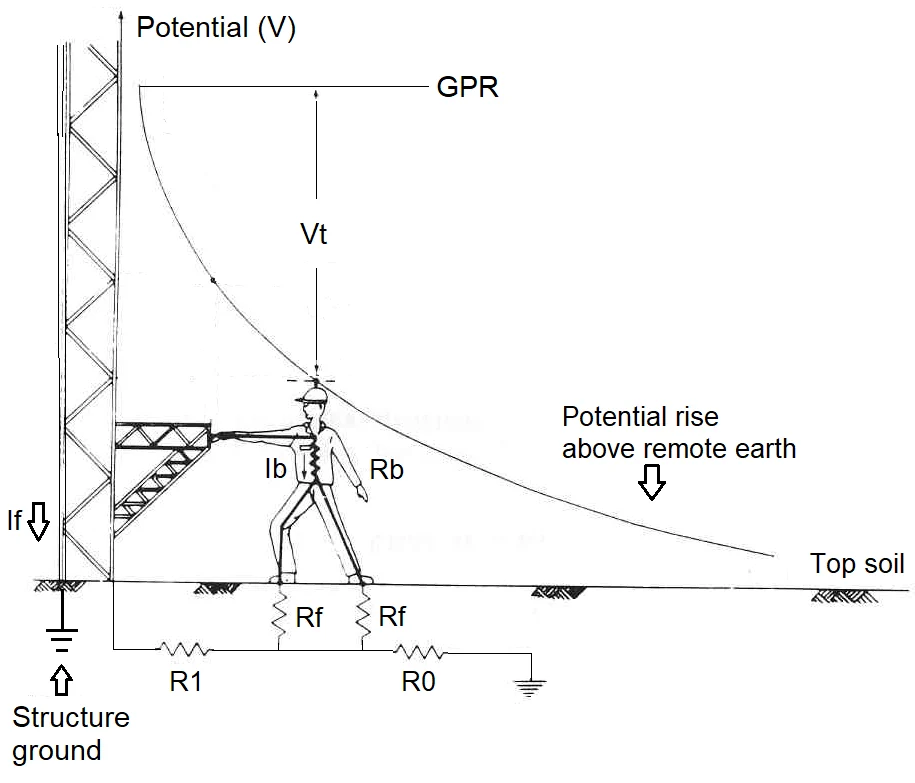
Fault current flowing into soil raises the potential of the earth grid above remote earth. This rise, called ground potential rise or GPR, spreads out as a voltage gradient across the surface.
The steeper the gradient, the higher the shock risk. Our guide on electrical shock explains why even short currents through the body can be fatal.
3 Lifesaving Checks in Earthing Design
GPR depends on grid resistance, found with methods from earthing resistance calculation, and on the part of fault current returning through soil.
If GPR is already below the tolerable touch limit, the design is safe with little extra analysis. Otherwise the detailed touch and step values must be calculated or simulated.
IEEE 80 Tolerable Limit Formulas
E step70 = (1000 + 6 × Cs × ρs) × 0.157 ÷ √ts
1000 Ω = body resistance, 0.157 = factor for a 70 kg person
ρs = surface resistivity, Cs = surface layer factor, ts = fault time
Example, bare soil 100 Ω·m, Cs = 1, ts = 0.5 s:
Touch = (1000 + 150) × 0.157 ÷ 0.707 = 255 V
Step = (1000 + 600) × 0.157 ÷ 0.707 = 355 V
With crushed rock 3000 Ω·m, Cs about 0.7:
Touch = (1000 + 3150) × 0.157 ÷ 0.707 ≈ 921 V
For a 50 kg person, IEEE 80 uses 0.116 instead of 0.157, giving lower and more conservative limits. Many utilities design to the 50 kg case for public areas.
The example shows why a crushed rock layer is so effective. It raises the tolerable touch limit several times by adding resistance in series with the feet.
Why Touch Voltage Usually Governs
The touch limit is lower than the step limit because current flows through the heart from hand to feet. The step path from foot to foot is less dangerous.
Touch voltage is usually highest at the corners of the grid and at fences. Fences need special care because people outside the substation can touch them.
Short fault clearing time also helps, because tolerable voltage rises as time falls. This links earthing to fast protection and short circuit current studies.
Methods to Reduce Touch and Step Hazards
Conductor size for the grid is chosen for fault current and duration, as in earth conductor size calculation. The layout then controls step and touch values.
Neutral earthing also affects fault current magnitude. Our article on neutral grounding resistor sizing shows how resistance earthing limits earth fault current.
Typical Surface Materials Compared
| Surface Material | Approximate Resistivity | Effect on Touch Limit |
|---|---|---|
| Wet soil | About 50 to 200 Ω·m | Low limit |
| Dry gravel | About 1000 to 3000 Ω·m | Much higher limit |
| Clean crushed rock | About 3000 Ω·m or more | High limit |
| Asphalt | Very high when dry | Very high limit |
Resistivity of surface materials varies with moisture and contamination. Use tested values for the actual material and assume wet conditions for design.
Keep the crushed rock layer clean and free of weeds. Soil mixing into the stones lowers resistivity and weakens protection over time.
Tolerable Touch and Step Calculator
Compare these limits with calculated or measured touch and step values from the grid study. The design passes only when actual values stay below both limits.
- Design to the 50 kg case in public areas.
- Use crushed rock over the whole yard.
- Bond fences and add outer ring conductors.
- Test earth grids periodically.
- Ignoring fence touch voltage.
- Using dry soil values for design.
- Forgetting transferred potentials on cables.
- Letting the rock layer become contaminated.
Touch and Step Potential Testing Note
Substation Grounding Video
Earth Fault Safety Questions
Related Articles
- Earthing Resistance Calculation
- Earth Conductor Size Calculation
- TN, TT and IT Earthing Systems
- Grounding Techniques Explained
- Electrical Shock Causes and Prevention
External References
- Tolerable Limits in Substation Grounding, EEPower
- Touch and Step Potential Testing, AEMC
- Touch and Step Voltage Calculations, EasyPower
- Earth Potential Rise, Wikipedia
What We Learn Today
- Fault current raises ground potential and creates dangerous surface gradients.
- IEEE 80 limits depend on body weight, surface resistivity and fault duration.
- Dense grids, crushed rock and fast clearing keep people safe.