
A shutdown valve that takes twelve seconds to close when the study allowed only four is a hidden hazard waiting for a real trip. Knowing where the air goes, and what slows it down, lets you measure, predict and shorten stroke time with confidence.
Every pneumatic valve needs time to fill or vent its actuator, and that time decides whether a loop responds well or a trip is safe. This guide explains the factors behind valve stroking time, how to measure it and seven proven ways to make a slow valve faster.
What Is Valve Stroking Time?
Valve stroking time is the time a valve takes to travel from one end position to the other after it receives a command, for example from fully open to fully closed. It is usually measured separately in the opening and closing directions, because a pneumatic valve actuator fills and vents through different paths.
For an on off safety valve, the command is normally the solenoid valve losing power, and the stroke ends when the limit switch confirms the final position. For a modulating process control valve, engineers also look at dead time and step response, but full stroke speed still matters for surge and pressure relief duties.
The total time includes three parts: the electrical delay of the logic and solenoid, the dead time before the actuator pressure has changed enough to overcome friction and spring preload, and the actual travel time. A good test records all three, not only the movement you see with your eyes.
Why Stroke Speed Matters in Plants
In an emergency shutdown system, the valve is usually the slowest part of the safety function. If the valve closes too late, the trip logic may be perfect and the hazard still happens, so valve stroking time is written into the safety requirements and checked during every proof test.
IEC 61511 asks that the response time of a safety instrumented function stays within the process safety time, the time between the start of a demand and the hazardous event. Many companies keep the full function response below about half of that time as a design margin, which leaves very little room for a slow valve.
Compressor antisurge valves, turbine bypass valves and pressure letdown valves also need fast travel, because a slow opening allows surge or overpressure within seconds. Emerson states in its Fisher SS 263 volume booster bulletin that such valves can need full stroke times under 2 seconds on positioner control and under 1 second on a solenoid trip.
In a Habonim case study, a fire safe ball valve on a 3 inch gas line was made to close in 120 milliseconds, including all electrical and mechanical delays. The standard actuator first needed 230 to 300 milliseconds.
Factors That Decide Valve Stroking Time
Air must move into or out of the actuator to change its position, so valve stroking time is mainly a question of how much air is needed and how fast the pneumatic path can carry it. The friction and torque of the valve itself add a smaller, but real, share.
Bigger diaphragm cases and longer piston strokes need more free air for every stroke.
Tubing bore, fittings, solenoid Cv and positioner output limit the flow.
Higher supply fills faster, while a weak regulator starves the actuator.
Tight packing, high seat torque and process pressure slow the start of travel.
Spring return actuators vent to close or open, so the exhaust path decides the fail safe stroke. The air volume of diaphragm and piston actuators differs a lot, and a piston type usually has a smaller volume for the same thrust because it runs at higher pressure.
Before you blame the actuator, read the supply gauge at the actuator port during a stroke. A sharp pressure dip there points to an undersized regulator, solenoid or tubing run, not to the valve.
Solenoid Valves, Tubing and Series Cv
The solenoid valve in an ESD hookup is often a small 1/4 inch body chosen for low power, and its Cv can be the narrowest point of the whole air path. When parts are in series, the combined flow coefficient is always lower than the smallest single one.
Example: solenoid Cv 1.5 in series with tubing and fittings Cv 4.0
1 ÷ 1.5² = 0.444, 1 ÷ 4.0² = 0.0625
Sum = 0.507, so Cv total = 1 ÷ √0.507
Cv total = 1.40, close to the solenoid alone
Long tube runs, sharp bends, small bore push in fittings and a partly blocked filter add hidden restrictions. Moisture also matters, because water and rust in the lines narrow the bore over the years, as explained in dew point risks in instrument air.
Estimating Stroke Time From Air Volume
A first estimate of valve stroking time treats the actuator as a tank that must be filled or emptied. The free air to move equals the actuator volume times the pressure change, divided by atmospheric pressure, and the time equals that free air divided by the average flow of the path.
Stroke time: t = Vfree × 60 ÷ Q
V = actuator volume in litres, ΔP = pressure change in bar
Q = average effective flow of the air path in NL/min
Example: V = 10 L, ΔP = 5.5 bar, Q = 600 NL/min
Vfree = 10 × 5.5 ÷ 1.013 = 54.3 NL
t = 54.3 × 60 ÷ 600 = 5.43 s
The average flow Q should be lower than the catalogue maximum, because flow falls as the actuator pressure approaches the supply or the atmosphere. Treat this result as a screening value and always confirm the final number by a field test.
Valve Stroking Time Calculator
Second Worked Example With a Quick Exhaust Valve
Suppose the safety study allows a closing time of 3 seconds for the same 10 litre actuator, and the field test confirms about 5.4 seconds. The solenoid exhaust path is the bottleneck, so a quick exhaust valve is fitted right at the actuator port.
If the quick exhaust valve raises the average venting flow to 3000 NL/min, the time becomes 54.3 × 60 ÷ 3000 = 1.09 s. The new valve stroking time meets the 3 second limit with a healthy margin, which the next proof test must confirm.
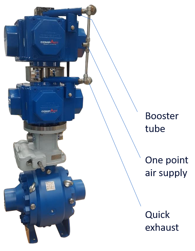
A quick exhaust valve vents the actuator directly to atmosphere at the port, so the air never travels back through the long tube and the small solenoid. That one change often removes most of the exhaust delay on spring return actuators.
7 Proven Fixes for a Slow Valve
A volume booster is a pneumatic relay that copies its small input signal but passes much larger supply and exhaust flows, which suits a control valve positioner on a large actuator. Its bypass needle must be set so the positioner stays stable and the valve does not hunt.
Emerson states that one Fisher SS 263 booster can replace up to three Fisher 2625 boosters and offers about three times their flow capacity. The same bulletin lists a maximum supply and exhaust Cv of 9.5 and a fixed 1 to 1 input to output ratio.
Never add a booster without its bypass adjustment set during commissioning. A booster that opens on every tiny positioner change makes a modulating valve overshoot and cycle.
How to Measure Valve Stroking Time on Site
A stopwatch is fine for a quick check of a slow valve, but a recorded test is far better for safety valves. Plant logic can timestamp the command and the limit switch change, and a sequence of events recorder gives millisecond resolution.
Smart positioners and partial stroke test devices also record travel against time. A partial stroke test can show a growing breakaway delay long before a full trip fails, which helps you plan maintenance.
Valve Stroking Time in ESD Proof Tests
Each proof test should compare the measured valve stroking time with the value written in the safety requirements and with earlier tests. A steady rise points to packing friction, a sticking solenoid or a degraded air path, all of which reduce SIS final element reliability.
- Valve tag, safety function and allowed closing time are on the test sheet.
- Supply pressure at the actuator port is recorded during the stroke.
- Command and limit switch signals are logged with timestamps.
- Opening and closing times are measured separately.
- Results are compared with the last three tests for trends.
- Any time above the limit is raised as a failure for the safety record.
Advantages and Limits of Faster Valves
- Safety functions act well inside the process safety time.
- Antisurge and relief duties respond before damage occurs.
- Better loop response on large modulating valves.
- Clear margin for ageing and dirty air over the years.
- Boosters and quick exhaust valves add cost and parts.
- High air demand can drop header pressure for other users.
- Very fast closing can cause water hammer or surge.
- Fast modulating valves can become unstable if poorly tuned.
Any change to valve stroking time on a safety valve is a modification under management of change, because the response time is part of the verified design. Recheck the SIL calculation if new parts such as boosters or extra solenoids enter the final element.
Common Mistakes and Troubleshooting Tips
If a valve suddenly becomes slow, check the solenoid first, then the regulator, the tubing and finally the actuator and packing. Guidance on mechanical causes is collected in valve torque and actuator failure and control valve troubleshooting.
Fisher SS 263 Volume Booster Bulletin
Volume Boosters on Valve Systems Video
Valve Stroking Time FAQ
It is the time a valve takes to move from one end position to the other after it receives a command. It is normally measured separately for opening and closing, because the air fills and vents through different paths.
The total includes electrical delay, dead time and actual travel time. Safety valves have a maximum value written in their safety requirements and checked at every proof test.
The valve is usually the slowest part of a safety instrumented function. If it closes too late, the hazard can still develop even when the logic acted perfectly.
IEC 61511 requires the function to respond within the process safety time. Many companies also keep a margin of about half that time for the whole function.
Large actuator volume, a small solenoid valve and long, narrow tubing are the usual causes. A weak regulator or low header pressure also starves the actuator during the stroke.
High packing friction and seat torque can add a delay before movement starts. Dirty or wet instrument air slowly narrows passages and makes things worse over time.
It sits at the actuator port and vents the air straight to atmosphere. The air no longer travels back through the long tube and small solenoid exhaust path.
On spring return actuators this often cuts the venting time by a large factor. It is a simple, low cost fix for slow fail closed or fail open valves.
A booster suits large actuators driven by a positioner that cannot supply enough air. It copies the positioner signal and passes much larger supply and exhaust flows.
Emerson states that its SS 263 booster helps large valves stroke in under 2 seconds on positioner control. The bypass must be tuned so that the valve stays stable.
Log the trip command and the limit switch signals together, then trip the valve. Read the dead time, travel time and total time from the recorded trend.
A sequence of events recorder or a smart positioner gives good millisecond resolution for this. Always test both directions and compare the result with earlier tests and the limit.
Yes, a very fast closing on a long liquid line can cause water hammer and pipe stress. Some compressor and pump systems can also be upset by sudden isolation.
Engineers then add a speed control valve or orifice in the exhaust path. The final speed must match the limits set by the surge or process study.
Related Articles
- Emergency Shutdown System ESD
- Partial Stroke Testing of ESD Valves
- Solenoid Valve Working Principle
- Control Valve Positioner Working
- SIS Final Element Reliability
External References
- Fisher SS 263 Volume Booster Product Bulletin, Emerson
- Emergency Shut Down Valve Automation for Large, High Torque Valves, Fluid Handling Pro
- Valve Actuator, Wikipedia
What We Learn Today
- Valve stroking time is the full time from command to end position, including electrical delay, dead time and actual travel, measured separately for opening and closing.
- Actuator volume, solenoid Cv, tubing, supply pressure and friction decide the speed, and parts in series always flow less than the smallest one.
- Quick exhaust valves, volume boosters, bigger solenoids and better tubing are proven fixes, but every change on a safety valve needs testing and management of change.
