
A large feeder can leak hundreds of milliamps to earth long before its breaker notices any overcurrent. An earth leakage relay watches that hidden residual current through a core balance CT and trips the breaker before the leak becomes a fire or a shock.
An earth leakage relay pairs a core balance current transformer with an adjustable relay to protect big LT feeders against earth leakage. This guide covers settings, wiring, testing and selection for Indian plants.
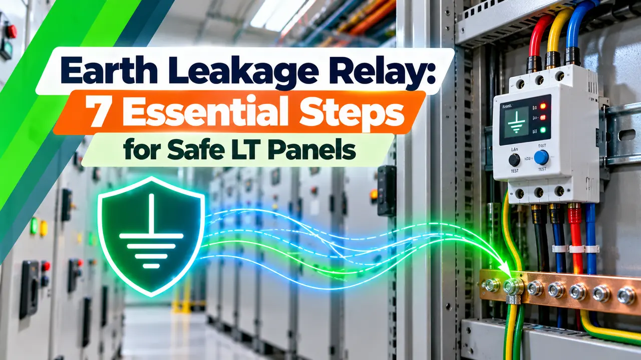
What Is an Earth Leakage Relay?
An earth leakage relay, usually called an ELR, is a protective relay that measures the residual current of a circuit through a core balance current transformer (CBCT) and operates an output contact when that current exceeds a set value. The contact trips a breaker fitted with a shunt trip or undervoltage release, unlike an RCCB or ELCB that sense and break in one body.
In a healthy circuit, the current going out on the phases returns on the phases and neutral, so the vector sum is zero. When insulation fails and some current flows to earth, the sum is no longer zero, and the CBCT produces a small secondary signal much like any current transformer does.
How an Earth Leakage Relay Works With a CBCT
The CBCT is a toroid with many secondary turns, and the primary is simply the bundle of live conductors passing through it. Because the protective earth conductor must stay outside the window, the leakage current that returns through earth is exactly what the CBCT sees.
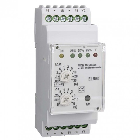
Modern relays measure the true RMS value of this residual signal, compare it with the setting and start a timer. Rayleigh lists a response under 30 ms at five times the set point and under 50 ms at the set point for its RI ELR60.
Rayleigh notes that IEC 60947 2 Annex M expects a failsafe output contact on such relays. The contact is held energised while healthy, so a lost auxiliary supply or broken coil also gives a trip or alarm.
ELR Settings: Sensitivity and Time Delay
Two knobs or menu values decide how the relay behaves: the rated residual operating current, often written IΔn, and the trip delay. Rishabh Instruments specifies a programmable range from 30 mA to 30 A with tripping at 80 to 100 percent of the set value on its RISH ELR series.
| Setting | Typical Use | Delay | Purpose |
|---|---|---|---|
| 30 mA | Final circuits, sockets, portable tools | Instantaneous | Protection against electric shock |
| 100 mA | Lighting boards, small sub distribution | Instantaneous or short | Additional protection, fire risk |
| 300 mA | Distribution feeders and DBs | 0.1 to 0.5 s | Fire protection, grading over 30 mA devices |
| 1 A to 3 A | Large feeders, MCC incomers | 0.5 to 1 s | Equipment and fire protection |
| 3 A to 30 A | Transformer LV incomers, PCC | 1 s and above | Backup and selectivity at the top level |
A 30 mA setting must always be instantaneous, because that level is chosen to protect people, as explained in electrical shock causes and effects. Higher settings with a delay are used upstream so that a downstream device clears its own fault first.
Before choosing the final setting, measure the standing leakage of the feeder with a leakage clamp meter. Keep it well below the setting, or the relay will trip on rainy days and motor starts.
ELR vs RCCB and ELCB: Which One Fits?
- Protects feeders of any current through the CBCT window.
- Adjustable sensitivity, often 30 mA to 30 A.
- Adjustable delay for selectivity.
- Alarm, pre alarm and display on digital models.
- Trips existing MCCB or ACB, no extra breaker.
- Sensing and breaking in one compact device.
- Fixed sensitivity, commonly 30 mA, 100 mA or 300 mA.
- Limited to modest current ratings.
- No adjustable delay in standard types.
- Cheaper for final circuits and homes.
For a home or office board, an RCCB is the natural choice. For a 400 A feeder in a factory, the practical choice is an earth leakage relay with a CBCT that trips the MCCB already selected for overload and short circuit duty.
7 Essential Steps to Install and Commission an Earth Leakage Relay
Rishabh limits the CBCT cable to under 1 m with a twisted shielded pair, so mount the relay close to the toroid. Long untwisted leads pick up noise from nearby power cables and cause random trips.
If a cable armour or screen is earthed at the load end and passes through the CBCT, earth fault current can return on it and cancel the signal. Route the armour back through the window or terminate it on the near side, following good earthing practice in industrial plants.
Leakage Margin and Earth Resistance Formula
Every healthy installation leaks a little through cable capacitance, filters and insulation. BS 7671 advises keeping this accumulated protective conductor current below 30 percent of IΔn, which is a sensible design target alongside good insulation.
Margin percent = total leakage ÷ IΔn × 100, target 30 percent or less
TT system check: RA × IΔn ≤ 50 V, so RA max = 50 ÷ IΔn
Example:
12 loads × 3.5 mA = 42 mA
Setting IΔn = 300 mA
Margin = 42 ÷ 300 × 100 = 14.0 percent
RA max = 50 ÷ 0.3 = 166.7 Ω
The second line applies in a TT system, where IEC 60364 asks that the product of electrode resistance and IΔn stays at or below 50 V. The earthing resistance calculation guide shows how to estimate RA for a pipe or plate electrode.
Leakage Margin Calculator
Second Worked Example: An Office Floor at 30 mA
Suppose ten desktop computers at about 1.5 mA each sit on one 30 mA circuit. The standing leakage is 15 mA, which is 50 percent of the setting and well above the 30 percent target.
Since the relay may trip anywhere from 80 to 100 percent of the setting, a small extra leak from a damp socket can push it over. The cure is to split the load over two or three circuits rather than raise the 30 mA protection.
Common Types of ELR
One factory set sensitivity and delay, simple and low cost.
Dial selected sensitivity and delay with a test button and LED bar.
Shows live leakage, pre alarm, event log and often RS485.
Detects AC and pulsating DC residual current.
Detection type matters more than many buyers realise. Rayleigh specifies Type A detection for its RI ELR60, while drives and rectifiers that feed smooth DC leakage may need special relays, so review the VFD manual before choosing.
On a digital earth leakage relay, set the pre alarm near 50 percent of IΔn. The alarm warns maintenance about slowly falling insulation weeks before an actual trip.
Where ELRs Are Used in Indian Plants
In a motor control centre, a relay with a CBCT on each large motor feeder catches winding insulation failure early. The same approach suits a pump house where water and cable joints share the same trench.
Earthing system type also matters. In a TN system the fault current is high and the breaker may already trip, while in TT and IT layouts described in TN, TT and IT earthing systems the ELR is often the main defence against earth faults.
Field Testing of an ELR
- Press the front test button and confirm the breaker trips.
- Pass a test wire through the CBCT and inject a known current.
- Check trip at or below the set IΔn value.
- Measure trip time against the set delay.
- Confirm the CBCT open or short alarm works.
- Verify reset works only after the fault clears.
- Measure feeder insulation resistance after any trip.
- Record readings in the maintenance register.
Secondary injection with a single test wire through the toroid is quick and safe, because no live conductor is touched. After any genuine trip, perform an insulation resistance test on the outgoing cable and load before switching back on.
Troubleshooting Nuisance Tripping
Most nuisance trips come from high standing leakage, wrong conductor routing or induced noise. Start by measuring leakage with a clamp meter around all live conductors, then check that the neutral is not earthed again downstream.
Inrush of large motors or transformers can unbalance the CBCT if the conductors are not centred in the window. Centre the cable bundle, use a larger CBCT if needed and add a short delay, as with any protective relay coordination.
Harmonic filters and drive EMC filters often contain capacitors connected to earth. Their leakage adds up quickly when several drives share one feeder.
How to Select an ELR
Select by system voltage, auxiliary supply, sensitivity range, delay range, detection type, contact rating and CBCT window. Check that the CBCT and relay come from the same maker, because sensitivity and accuracy are tested as a pair.
Prefer relays tested to IEC 60947 2 Annex M, with failsafe output, CBCT supervision and a remote test input. Digital models with RS485 let SCADA log leakage trends.
RISH ELR Datasheet
ELR and CBCT Explained on Video
Earth Leakage Relay FAQ
It is a protective relay that measures residual current through a core balance current transformer. When the leakage exceeds the setting for the chosen delay, its output contact trips a breaker.
The relay does not carry any load current itself. This allows one small DIN rail unit to protect a feeder of almost any current rating in an LT panel.
An RCCB senses leakage and breaks the circuit inside one compact device with a fixed sensitivity. An ELR only senses and signals, so it always needs a breaker fitted with a shunt trip.
The ELR also offers adjustable sensitivity and adjustable delay settings. That makes it the usual choice for large LT feeders where selectivity between levels really matters.
All phase conductors and the neutral must pass together through the same CBCT window. The protective earth conductor must always stay outside that window.
If the earth wire also goes through, fault current returns through the toroid and cancels itself. The relay then fails to see a real fault and the feeder remains unprotected without anyone noticing.
Use 30 mA with no delay for shock protection on final circuits and sockets. Use 100 mA to 300 mA for fire protection on distribution feeders and boards.
Large incomers often use settings of a few amperes with a time delay. These settings should grade with downstream devices so that the device nearest the fault trips first.
Common causes are high standing leakage, a neutral earthed again downstream and noise on long CBCT leads. Cables that sit off centre in the window during motor inrush can also give a false signal.
Measure leakage with a clamp meter and correct the conductor routing first. Keep the CBCT cable short and use a twisted shielded pair as the maker advises.
Press the test button to check the output contact and the breaker trip coil together. Then pass a separate test wire through the CBCT and inject a known current.
Compare the measured trip current and trip time with the relay settings. Record the results along with the date in the maintenance register kept for each panel.
IEC 60947 2 Annex M covers residual current protection devices used together with circuit breakers. Leading makers such as Rishabh state testing to this annex in their published datasheets.
The annex also expects a failsafe output, so a supply failure is noticed quickly. Installation rules come from IEC 60364 and from the Indian wiring code, IS 732.
Related Articles
- MCB vs MCCB vs ELCB vs RCCB
- Current Transformer Working Principle
- TN, TT and IT Earthing Systems
- Earth Fault Loop Impedance Zs Testing
- Protective Relays Explained
External References
- RISH ELR Earth Leakage Relay Datasheet, Rishabh Instruments
- RI ELR60 Earth Leakage Relay With Adjustable Trip, Rayleigh Instruments
- Residual Current Device, Wikipedia
What We Learn Today
- An earth leakage relay measures residual current through a CBCT and trips an MCCB or ACB through its shunt trip when leakage crosses the set value.
- Typical settings run from 30 mA instantaneous for shock protection up to several amperes with delay for large LT incomers and selectivity.
- Keep standing leakage under about 30 percent of the setting, keep the PE conductor outside the CBCT and test the relay with a test loop regularly.