
A thermocouple that read perfectly on day one can quietly read several degrees wrong a year later, with no alarm and no visible damage. Understanding why the wires change lets you choose better sensors, schedule smart checks and trust your furnace readings again.
Thermocouple wires change their thermoelectric properties with heat, time and atmosphere, so the output slowly moves away from the reference table. This guide explains every cause of thermocouple drift and the practical steps that keep it under control.

What Is Thermocouple Drift?
Thermocouple drift is the slow change in the voltage that a thermocouple produces for a given temperature, caused by physical and chemical changes in the wires during service. The sensor still works and still gives a believable value, which is exactly why the error often goes unnoticed, as discussed in temperature sensor failure warning signs.
A thermocouple does not generate its voltage at the tip. The EMF is produced along every part of the wire that sits in a temperature gradient, as explained in basics of thermocouples and RTD, so any change in the wire inside that gradient zone changes the reading.
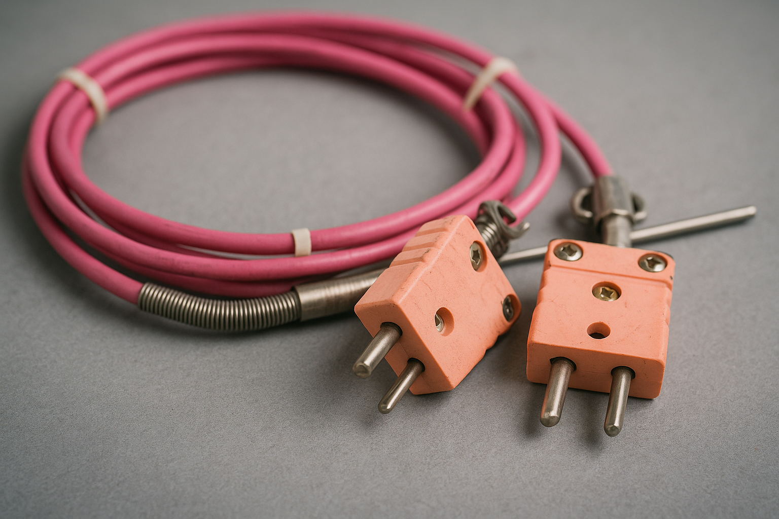
When a section of wire is heated for long periods, its alloy composition or crystal structure changes, and the wire becomes inhomogeneous. That changed section then generates a different voltage, and thermocouple drift appears whenever it lies in a gradient, so the reading depends on how deep the probe sits.
Thermocouple drift is mainly a property of the wire in the hot to cold transition zone, not of the junction. Replacing only the tip weld does not remove an error that lives a few hundred millimetres back along the wires.
6 Hidden Causes of Thermocouple Drift
Local changes in alloy or structure along the wire.
Chromium or aluminium oxidise and leave the wire.
Chromium oxidises in low oxygen, wire turns green.
Atoms in the Type K positive leg rearrange.
Sulphur, phosphorus or metal vapour diffuse in.
Bending and stretching change the wire structure.
All six causes produce the same symptom, which is inhomogeneity in the zone where the temperature changes. The difference lies in the temperature band, the atmosphere and whether the change can be reversed by heat treatment, which affects how you choose from the types of thermocouples and ranges.
Short Range Ordering and Type K Thermocouple Drift
Type K wire uses a nickel chromium positive leg and a nickel aluminium negative leg. Cleveland Electric Laboratories notes that between roughly 200 and 600 °C, the atoms in the positive leg form an ordered structure, an effect called short range ordering.
According to the same source, this can cause measurement errors of up to 4 to 5 °C. JMS Southeast describes the same effect in a brick plant study and adds that the error appears only where the ordered wire lies in a temperature gradient.
Short range ordering is partly reversible, since heating the wire above about 700 °C and cooling it quickly can restore the disordered state. In practice, a Type K sensor that sits for months in the middle band will drift and then partly recover when the process heats up again, which makes the error confusing.
If a Type K sensor measures a process held between 250 and 550 °C for long periods, consider Type N or an RTD instead. Most of the ordering problem disappears with that one specification change.
Oxidation, Green Rot and Thermocouple Drift
In air above about 800 °C, chromium and aluminium in base metal wires slowly oxidise, and the composition of the surviving metal changes. The negative and positive legs change at different rates, so the output falls or rises depending on the alloy, as noted in thermocouple types comparison.
Green rot is a special case that occurs when there is too little oxygen to form a protective layer, for example inside a sealed sheath or a reducing furnace. Chromium oxidises preferentially, the wire turns green and brittle, and the positive leg loses its thermoelectric output fast.
Venting the protection tube, using a getter or choosing Type N reduces green rot risk. Mineral insulated cable with an Inconel sheath also helps, though the right thermowell and sheath material must suit the furnace gas.
How Fast Does a Thermocouple Drift?
The rate of thermocouple drift depends strongly on temperature, atmosphere, wire size and sheath design, so no single number fits every plant. A 2022 study by NPL and other European metrology institutes tested sensors at 1200 °C for 500 hours.
In that study, conventional Type N thermocouples drifted by an average of minus 2.7 °C, while dual wall Type N sensors drifted only minus 0.9 °C. Conventional Type K sensors at the same condition averaged minus 2.3 °C.
The same paper reported that two conventional Type K sensors failed during thermal cycling, while all dual wall samples survived. Results like these show that thermocouple drift depends on sheath construction and wire choice as much as on the thermocouple letter.
Base metal thermocouples age fastest during the first hours at a new high temperature. Many furnace users therefore pre age new sensors at working temperature before trusting them for control.
Estimating Recalibration Interval From Drift
If you record the error found at each check, you can estimate a thermocouple drift rate and plan the next check before the sensor leaves its tolerance. The same logic is used in calibration interval determination for ISO 9001.
Months to limit = allowed error ÷ drift rate
Suggested check interval = months to limit ÷ 2
Example:
Allowed error = 2.5 °C, measured drift = 0.8 °C after 6 months
Drift rate = 0.8 ÷ 6 = 0.13 °C per month
Months to limit = 2.5 ÷ 0.1333 = 18.8 months
Check interval = 18.8 ÷ 2 = 9.4 months
The allowed error of 2.5 °C comes from IEC 60584 Class 2 for Type K below 333 °C. Halving the time to the limit gives a simple safety margin, because drift is rarely linear and often speeds up as the wire ages.
Thermocouple Drift Interval Calculator
Second Worked Example: Heat Treatment Furnace
A Type K sensor in a 900 °C furnace has an allowed error of 0.0075 × 900 = 6.75 °C under IEC 60584 Class 2. A comparison check after 4 months shows thermocouple drift of 1.5 °C, with the sensor reading low.
The drift rate is 1.5 ÷ 4 = 0.375 °C per month, so the limit is reached after 18 months and a check every 9 months looks acceptable. If the furnace qualification demands a tighter limit, such as 3 °C, the interval drops to 4 months and replacement becomes cheaper than testing.
How to Detect Thermocouple Drift in the Field
The most reliable method is an in situ comparison, where a freshly calibrated reference sensor is inserted next to the service sensor at the same depth. A multipoint thermocouple or a spare thermowell makes this much easier.
Removing the sensor and checking it in a dry block calibrator can mislead, because the aged wire section may sit in a different gradient in the block. If you must test in the lab, vary the immersion depth and watch whether the reading changes, which is a classic inhomogeneity test.
- Compare with a reference sensor at the same immersion depth.
- Change immersion depth and look for a shift in reading.
- Compare redundant sensors in the same zone over time.
- Trend the difference between control and recorder sensors.
- Check the cold junction compensation and transmitter first.
- Inspect the sheath for scaling, bending and discolouration.
- Record each check to build a drift history.
Before blaming thermocouple drift, rule out faults in cold junction compensation and in the thermocouple extension wire. Wrong compensating cable or a hot terminal head can look exactly like sensor drift.
Proven Ways to Prevent Thermocouple Drift
Cleveland Electric Laboratories reports that Type N held within ± 0.5 °C over hundreds of hours of cycling and can last up to 300 percent longer than Type K. It costs about 10 to 15 percent more, which is small compared with a scrapped furnace load, as discussed in thermocouple selection.
For very tight accuracy at moderate temperatures, an RTD is often the better choice, and thermocouple vs RTD compares the two. Noble metal Type R and S sensors drift less but can be poisoned by silicon or metal vapour.
Never reuse an aged Type K sensor at a shallower immersion depth. The degraded wire section moves into the gradient and the reading jumps, sometimes by several degrees.
- Keeps furnace and reactor control accurate.
- Protects product quality and heat treatment records.
- Turns sensor replacement into planned work.
- Supports audit requirements such as AMS 2750.
- Drift is invisible without a reference check.
- Lab recalibration may not show the field error.
- Better sensors and sheaths cost more upfront.
- Drift rate is rarely linear over time.
Where Thermocouple Drift Control Matters Most
In each of these, a small bias can waste energy or product without any alarm, so drift checks belong in the routine plan described in how to improve thermocouple accuracy.
NPL Study on Type K and N Stability
Detecting Drift on Video
Thermocouple Drift FAQ
It is the slow change in the voltage a thermocouple produces at a given temperature during service. The wires change chemically or physically, so the reading moves away from the standard table.
The sensor keeps working and the value still looks believable on the screen. That makes the error dangerous, because nobody notices it without a reference check.
In that band, atoms in the nickel chromium positive leg form an ordered structure. This short range ordering changes the voltage of any wire section that sits in a temperature gradient.
Cleveland Electric Laboratories reports errors of up to 4 to 5 degrees from this effect. Heating the wire above about 700 degrees can partly reverse it, which makes the drift confusing.
Green rot is a severe form of thermocouple drift caused by preferential oxidation of chromium in the positive leg when oxygen is scarce. It often happens inside sealed tubes or in reducing furnace atmospheres.
The wire turns green and brittle, and its output drops quickly. Venting the tube, using a getter or choosing Type N wire reduces the risk.
Type N was developed to avoid short range ordering and to resist oxidation far better than the older alloy. It stays more stable across the common industrial range from 200 to 1200 degrees.
Cleveland Electric Laboratories reports stability within half a degree over hundreds of hours of cycling. The price premium is usually only 10 to 15 percent.
The changed wire section lies in the temperature gradient of the process, not at the tip. In a dry block, that section may sit in a different gradient and give a different error.
An in situ comparison with a reference sensor at the same depth is more reliable. Varying immersion depth in the lab can also reveal inhomogeneity.
There is no single interval, because drift depends on temperature, atmosphere and sensor design. Record the error at each check and calculate a drift rate in degrees per month.
Then set the next check at about half the time it takes to reach the allowed error. High temperature furnace sensors often need checks every few months.
Rewelding the junction does not fix wire that has changed along its length. Short range ordering can be partly reversed by heat treatment, but oxidation and contamination are permanent.
In most plants, replacing the whole sensor is cheaper and safer than any attempt at repair. Keep spares calibrated and pre aged so a swap takes only a short shutdown window.
Related Articles
- How to Improve Thermocouple Accuracy
- Thermocouple Types Comparison
- Types of Thermocouples and Ranges
- Cold Junction Compensation in Thermocouple
- Thermocouple Burnout Detection
External References
- Thermoelectric Stability of Dual Wall and Conventional Type K and N Thermocouples, NPL
- Type K vs Type N Thermocouples, Cleveland Electric Laboratories
- Thermocouple, Wikipedia
What We Learn Today
- Thermocouple drift comes from wire changes in the temperature gradient zone, so the error depends on immersion depth rather than on the junction alone.
- Type K suffers short range ordering between about 200 and 600 °C and green rot in low oxygen, while Type N resists both effects.
- A recorded drift rate lets you set a sensible check interval, and in situ comparison reveals field error better than a lab bath.