
A safety function can have an excellent PFD on paper and still fail its SIL claim because the architecture is too thin. Learn how HFT and safe failure fraction set the minimum redundancy for every sensor, logic solver and valve.
Architectural constraints decide how much redundancy a safety instrumented function must have, regardless of how good its PFD calculation looks. This guide explains HFT, SFF, Type A and B elements and both IEC 61508 routes with worked examples.
What Is Hardware Fault Tolerance?
Hardware fault tolerance is the number of dangerous hardware faults a subsystem can suffer while still performing its safety function, so HFT 0 means one dangerous fault can disable it. It is one of the three pillars of SIL verification, alongside random failure probability and systematic capability.
PR electronics puts it simply: 1oo1 equals HFT 0 and 1oo2 equals HFT 1. In other words, HFT counts redundant channels, and the voting arrangements covered in voting architectures in safety systems are how engineers build it in practice.
The requirement is called an architectural constraint because it limits the SIL you may claim for a given architecture. Even if your PFD average meets the target band in the SIL table, a single channel valve cannot be claimed for SIL 3 under IEC 61511 without the redundancy the table demands.
Before the 2010 second edition of IEC 61508, there were no separate Route 1H and Route 2H options. exida notes that the revision also removed no effect failures from the SFF calculation, so manufacturers could no longer inflate SFF by adding extra components.
MooN Voting and HFT Relationship
For any M out of N voting group, HFT equals N minus M. The group trips when M channels demand a trip, so N minus M channels can fail dangerously and the function still works.
| Voting | Channels | HFT | Main Benefit | Main Weakness |
|---|---|---|---|---|
| 1oo1 | 1 | 0 | Simple, low cost | One dangerous fault defeats it |
| 1oo2 | 2 | 1 | High safety | Spurious trip if either channel fails safe |
| 2oo2 | 2 | 0 | Few spurious trips | One dangerous fault defeats it |
| 2oo3 | 3 | 1 | Safety plus availability | More hardware and wiring |
| 1oo3 | 3 | 2 | Highest safety | Highest spurious trip tendency |
Notice that 2oo2 has two transmitters but still an HFT of 0, because a single dangerous failure blocks the trip. The popular 2oo3 voting logic gives HFT 1 and also tolerates one safe failure without tripping the plant.
When you write the safety requirements, state the HFT for each subsystem separately: sensors, logic solver and final elements. A SIF is only as fault tolerant as its weakest subsystem.
Safe Failure Fraction and How It Is Calculated
Safe failure fraction, or SFF, is the share of all failures that are either safe or dangerous but detected by diagnostics. PR electronics describes it as the percentage of safe and dangerous detected failures versus total failures, and our article on safe failure fraction covers it in more depth.
DC = λDD ÷ (λDD + λDU) × 100
λ values in FIT, where 1 FIT = 1 failure per 10⁹ hours
Example, smart transmitter:
λS = 300 FIT, λDD = 450 FIT, λDU = 50 FIT
Total = 300 + 450 + 50 = 800 FIT
SFF = 750 ÷ 800 × 100 = 93.75 percent
DC = 450 ÷ 500 × 100 = 90 percent
Type B, SFF 90 to 99 percent, HFT 1 gives up to SIL 3
The λ values come from the FMEDA report or certificate of the device. A high SFF tells you that most dangerous faults will be caught by diagnostics and turned into an alarm or safe action, leaving few undetected dangerous failures.
Type A and Type B Elements
Simple device with well defined failure modes and behaviour under fault, with solid field data.
Complex device, usually with a microprocessor or software, where some failure modes are not fully known.
The type matters because Route 1H allows a Type A element a higher SIL than a Type B element at the same SFF and HFT. A SIS final element made of a valve, actuator and solenoid is usually Type A, while a smart positioner added to it is Type B.
Route 1H Hardware Fault Tolerance Tables
Route 1H, from IEC 61508 Part 2, uses the device type and its SFF to find the maximum SIL allowed for each HFT. The two tables below are the heart of hardware fault tolerance under Route 1H.
| SFF | Type A HFT 0 | Type A HFT 1 | Type A HFT 2 | Type B HFT 0 | Type B HFT 1 | Type B HFT 2 |
|---|---|---|---|---|---|---|
| Below 60 % | SIL 1 | SIL 2 | SIL 3 | Not allowed | SIL 1 | SIL 2 |
| 60 to 90 % | SIL 2 | SIL 3 | SIL 4 | SIL 1 | SIL 2 | SIL 3 |
| 90 to 99 % | SIL 3 | SIL 4 | SIL 4 | SIL 2 | SIL 3 | SIL 4 |
| 99 % and above | SIL 3 | SIL 4 | SIL 4 | SIL 3 | SIL 4 | SIL 4 |
Read the table as a ceiling. If a Type B transmitter has an SFF of 85 percent, one transmitter can support at most SIL 1, and a 1oo2 pair can support at most SIL 2.
Route 2H and Proven Field Data
Route 2H replaces the SFF tables with a fixed HFT per SIL, but only when failure rate data is collected from similar applications and environments. exida stresses that the data must reach a 90 percent statistical confidence level, which needs a disciplined field feedback system.
Under Route 2H, SIL 4 needs HFT 2, SIL 3 needs HFT 1, SIL 2 needs HFT 1 in high demand mode and HFT 0 in low demand mode, and SIL 1 needs HFT 0. Mirek Generowicz of TÜV Rheinland notes that this route lets SIL 3 be met with two valves instead of three.
His paper also points out that failure rates stated at 90 percent confidence are typically about 1.6 times higher than those at 70 percent confidence. The price of the simpler architecture is therefore a more conservative PFD calculation.
PR electronics notes that IEC 61511 clause 11.4.9 accepts reliability data at a 70 percent upper confidence limit for its own prior use route. That is lower than the 90 percent confidence demanded by Route 2H in IEC 61508.
IEC 61511 2016 Hardware Fault Tolerance Table
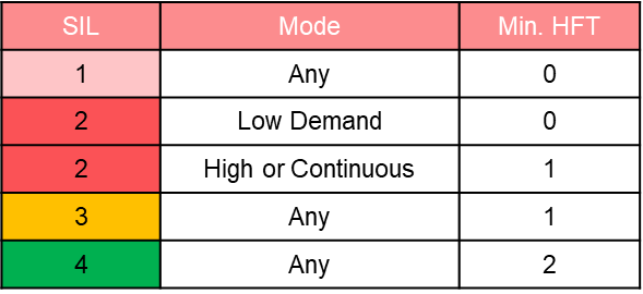
The 2016 edition of IEC 61511 Part 1 simplified the process sector rules into a single table, similar to Route 2H. It applies to the whole subsystem, whether the elements are Type A or Type B.
| SIL | Demand Mode | Minimum HFT | Typical Architecture |
|---|---|---|---|
| SIL 1 | Any mode | 0 | 1oo1 sensor and valve |
| SIL 2 | Low demand | 0 | 1oo1 with good data |
| SIL 2 | High or continuous | 1 | 1oo2 or 2oo3 |
| SIL 3 | Any mode | 1 | 1oo2 or 2oo3 |
| SIL 4 | Any mode | 2 | 1oo3, rarely used in process |
The standard also allows the required HFT to be reduced by one for SIL 1 to SIL 3 where added redundancy would cause more process safety problems, for example extra spurious trips during a dangerous startup. Such a decision must be justified and recorded, and it is reviewed during the functional safety assessment.
5 Essential Rules for HFT Compliance
These five rules keep hardware fault tolerance checks repeatable from one SIF to the next. Use the same route for every subsystem of a SIF unless your company procedure clearly allows mixing, and keep the risk target from LOPA SIL assessment at the top of the worksheet.
Safe Failure Fraction Calculator
Second Worked Example: Shutdown Valve for SIL 3
Consider a fail safe shutdown valve assembly treated as a Type A element with λS = 200 FIT, λDD = 0 FIT and λDU = 600 FIT, since a valve has no automatic diagnostics without partial stroke testing. Its SFF is 200 ÷ 800 × 100 = 25 percent.
Under Route 1H, a Type A element below 60 percent SFF needs HFT 2 for SIL 3, which means three valves in series. Under IEC 61511 Table 6 or Route 2H with good field data, two valves in 1oo2 give HFT 1 and meet the requirement, and partial stroke testing can still improve the PFD.
Before you add a third valve to satisfy Route 1H, check whether your plant procedure allows IEC 61511 Table 6 with prior use data. Fewer valves often mean fewer leak paths, lower spurious trip rates and simpler maintenance.
Common Hardware Fault Tolerance Mistakes
Common cause is the quiet enemy of redundancy. Two transmitters on one impulse line, or two valves supplied by one air header, behave closer to one channel, so use separate tapping points and review shared utilities as you would in emergency shutdown system design.
Field Checklist for HFT Verification
- SIL and demand mode confirmed for every SIF in the SRS.
- Voting of each subsystem written as MooN with its hardware fault tolerance.
- Device type A or B taken from the certificate or FMEDA.
- SFF and DC values recorded with the data source.
- Route 1H, Route 2H or IEC 61511 Table 6 stated clearly.
- Common cause sources checked: taps, power, air, cables.
- Any HFT reduction justified and approved.
- Proof test interval and coverage linked to the PFD calculation.
- Survives one or more dangerous faults.
- Protects against optimistic failure data.
- 2oo3 also cuts spurious trips.
- Allows online repair of one channel.
- More hardware cost and wiring.
- 1oo2 and 1oo3 raise spurious trip tendency.
- Common cause can defeat redundancy.
- More devices to proof test and maintain.
Where Hardware Fault Tolerance Matters Most
For Indian refineries, fertiliser plants and petrochemical units, HFT reviews usually take place during detailed engineering and again at the FAT. Clear separation of SIS and control hardware, explained in SIS and BPCS differences, makes the HFT argument much easier to defend.
Architectural Constraints Paper and Video
Hardware Fault Tolerance FAQ
It is the number of dangerous hardware faults a subsystem can tolerate while still performing its safety function. An HFT of 1 means the function survives any single dangerous fault.
It is calculated as N minus M for an M out of N voting group. A 1oo2 pair therefore has HFT 1, while a 2oo2 pair has HFT 0.
Safe failure fraction is the share of all failures that are safe or dangerous but detected by diagnostics. It is calculated from the λS, λDD and λDU values in the FMEDA report.
A high SFF means few dangerous failures remain hidden. Under Route 1H, a higher SFF lets the same device support a higher SIL with the same redundancy.
Route 1H finds the allowed SIL from the element type, its SFF and the fault tolerance of the design. It uses two tables in IEC 61508 Part 2, one for Type A and one for Type B elements.
Route 2H instead sets a fixed HFT for each SIL level and demand mode. It requires field failure data collected from similar applications with 90 percent statistical confidence.
The 2016 edition of IEC 61511 requires a minimum HFT of 1 for SIL 3 in any demand mode. In practice that means a 1oo2 or 2oo3 arrangement for sensors and final elements.
SIL 1 needs HFT 0, and SIL 2 needs HFT 0 in low demand mode. SIL 2 in high demand mode needs HFT 1, and SIL 4 needs HFT 2.
Not always, because the type only describes how well the failure behaviour is understood. Type A devices are simple, while Type B devices contain software or complex electronics.
Under Route 1H, Type A gets a higher SIL ceiling at the same safe failure fraction. A Type B smart transmitter with strong diagnostics can still reach a high SFF and a high SIL claim.
IEC 61511 allows a reduction of one in the required HFT for SIL 1 to SIL 3 in specific cases. The usual reason is that extra redundancy would create more process safety problems than it solves.
The justification must be documented and approved by competent people. It is checked again during the functional safety assessment before the system is put into service.
No, redundancy only helps if the channels fail independently of each other. A shared impulse line, power supply or instrument air header can disable every redundant channel at once.
Use separate process taps, diverse routing and independent utilities where possible. The PFD calculation should also include a realistic beta factor for the remaining common cause.
Related Articles
- SIL Verification
- Voting Architectures in Safety Systems
- Safe Failure Fraction Explained in Functional Safety
- What Is 2oo3 Voting Logic
- SIS Final Element Reliability
External References
- Achieving Compliance in Hardware Fault Tolerance, Mirek Generowicz, 61508 Association
- SIL Part 2, Architectural Constraints, PR electronics
- IEC 61508, Wikipedia
What We Learn Today
- Hardware fault tolerance is the number of dangerous faults a subsystem can survive, and for any MooN voting group it equals N minus M.
- Safe failure fraction is (λS + λDD) ÷ (λS + λDD + λDU), and Route 1H uses it with the Type A or B tables.
- IEC 61511 2016 requires HFT 1 for SIL 3 and HFT 0 for SIL 1, close to Route 2H, which needs field data at 90 percent confidence.