
When several bits of a binary count change together, a sensor or a second clock domain can catch them halfway and read a value that never existed. A reflected binary sequence changes only one bit per step, so that kind of false reading simply cannot happen.
Gray code is a binary numbering order in which neighbouring values differ in exactly one bit. That one property makes it the favourite output of absolute encoders and a safe way to pass counters between clock domains.

What Is Gray Code?
Gray code is an ordering of binary numbers in which every two consecutive values differ in only one bit position. It is also called the reflected binary code, and it sits beside BCD and plain binary in any study of number systems.
Unlike ordinary binary, the bits of this code do not carry place values such as 8, 4, 2 and 1. It is a code for positions and states rather than for arithmetic, much like the binary coded decimal format is a code for decimal digits.
The code is named after Frank Gray, a researcher at Bell Labs who patented it for pulse code communication. Today the same idea protects position readings in machines, motion systems and digital chips.
Why Does Binary Counting Cause Errors?
Look at the step from 7 to 8 in 4 bit binary, where 0111 becomes 1000 and all four bits change together. Real contacts, optical tracks or logic paths never switch at exactly the same instant, so for a short time the reading can be 1111, 0000 or any mix.
Control.com explains that in a plain binary sequence this possible error happens every other count. A controller that samples during such a transition may see a position that is completely wrong, then jump back on the next scan.
In Gray code, 7 is 0100 and 8 is 1100, so only the leftmost bit moves. If the sample lands during the transition, the reading is either the old value or the new value, and both are genuine neighbours.
Frank Gray filed his patent in 1947 and it was granted in 1953 under the title Pulse Code Communication. The name reflected binary comes from the way the sequence mirrors itself at every power of two.
Gray Code Table From 0 to 15
| Decimal | Binary | Gray Code | Bit That Changed |
|---|---|---|---|
| 0 | 0000 | 0000 | none |
| 1 | 0001 | 0001 | bit 0 |
| 2 | 0010 | 0011 | bit 1 |
| 3 | 0011 | 0010 | bit 0 |
| 4 | 0100 | 0110 | bit 2 |
| 5 | 0101 | 0111 | bit 0 |
| 6 | 0110 | 0101 | bit 1 |
| 7 | 0111 | 0100 | bit 0 |
| 8 | 1000 | 1100 | bit 3 |
| 9 | 1001 | 1101 | bit 0 |
| 10 | 1010 | 1111 | bit 1 |
| 11 | 1011 | 1110 | bit 0 |
| 12 | 1100 | 1010 | bit 2 |
| 13 | 1101 | 1011 | bit 0 |
| 14 | 1110 | 1001 | bit 1 |
| 15 | 1111 | 1000 | bit 3 |
Notice that 15 back to 0 also changes only one bit, which is why Gray code is called cyclic. This wrap around property is essential for a rotating encoder disc, where the last position sits right next to the first.
You can build the table by reflection. Write the 1 bit list 0 and 1, mirror it to get 0, 1, 1, 0, put 0 in front of the first half and 1 in front of the mirrored half, and repeat for each extra bit.
Binary to Gray Code Conversion With XOR
The fastest method uses the exclusive OR operation from digital logic gates. The most significant Gray bit equals the most significant binary bit, and every other Gray bit is the XOR of that binary bit and the binary bit to its left.
G(msb) = B(msb), G(i) = B(i+1) XOR B(i)
Example: decimal 13, 4 bits
Binary B = 1101
B shifted right = 0110
1101 XOR 0110 = 1011
Gray code of 13 = 1011, which reads as decimal 11
In hardware, an n bit converter needs just n minus 1 XOR gates and no clock. In C or structured text, the whole conversion is one line, g equals b XOR (b shifted right by 1).
When converting by hand, write the binary number, then write the pairs of neighbouring bits below it. Mark 1 where the pair differs and 0 where it matches, and you have the Gray bits without any table.
Gray to Binary Decoding Method
Decoding runs in the opposite direction and depends on the previous result. The most significant binary bit equals the most significant Gray bit, and each next binary bit is the XOR of the binary bit just found and the next Gray bit.
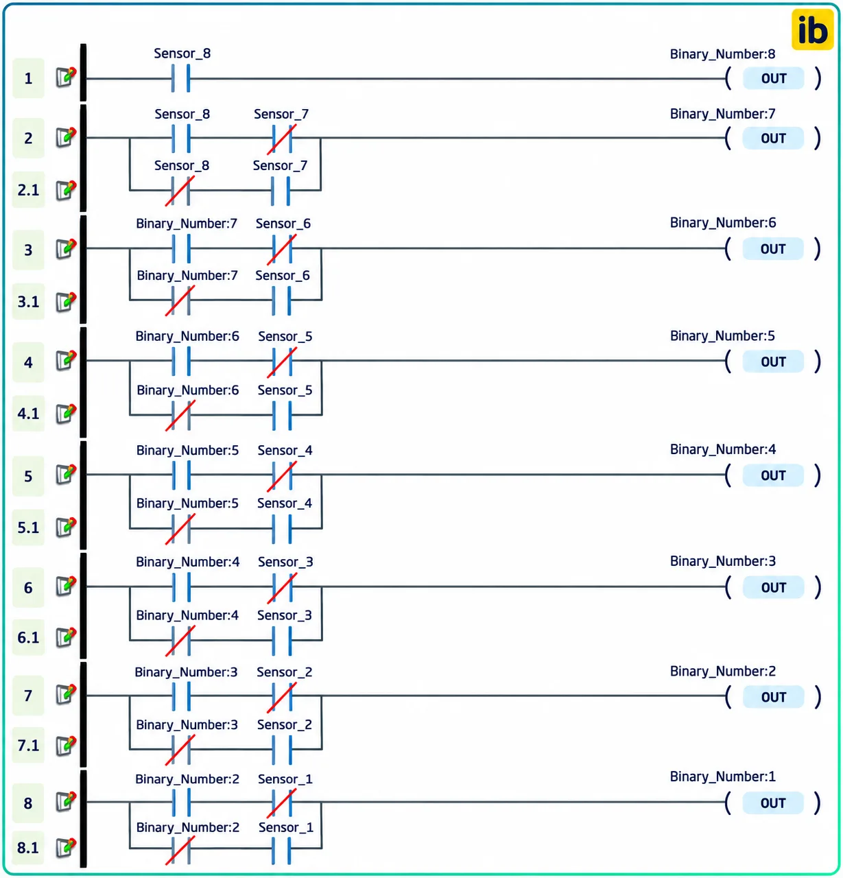
The Encoder Products Company white paper describes three ways to do this decoding: by hand on paper, in a software routine and in PLC ladder logic built from exclusive OR contacts. The ladder approach suits older controllers that lack a bitwise XOR instruction, and it follows the rules of Boolean algebra.
Gray Code Converter Calculator
Try the value 7 and then 8 with 4 bits and compare the outputs. The Gray code outputs are 0100 and 1100, which confirms that only one bit changes even though the binary form changes all four.
Gray Code in Absolute Encoders
An absolute encoder reads a disc with several concentric tracks, one track per bit, so it knows its position immediately at power up. The difference from pulse counting types is covered in incremental vs absolute encoders.
Control.com notes that typical absolute encoders have between 256 and 1024 unique patterns around the circle, which means an 8 bit or 10 bit output. The Encoder Products Company white paper calls Gray code the most popular absolute encoder output format.
The PLC or drive receives the parallel bits, converts them to binary and scales them to degrees or millimetres. For fast incremental channels, the same controller would use a PLC high speed counter instead.
One wire per bit, read directly by digital inputs.
Bits are clocked out serially, often still in reflected form.
Encoder converts internally and sends a binary position.
When a parallel encoder shows random jumps, check whether the PLC program expects binary while the encoder is set to the reflected format. A mismatch produces a staircase of wrong values that looks exactly like a wiring fault.
6 Essential Uses of Gray Code
In a Karnaugh map, the rows and columns are labelled 00, 01, 11, 10. That order guarantees that physically adjacent cells differ by one variable, which is exactly what lets you circle groups and simplify logic.
In low power design, a counter built this way toggles only one flip flop per clock. The fewer transitions reduce dynamic power compared with the ripple and synchronous counters that use natural binary.
Gray labelling is standard in QAM and PSK radio modulation. A noise error usually moves a symbol to a neighbouring point, and with this labelling that costs only one wrong bit instead of several.
FIFO Pointers and Clock Domain Crossing
An asynchronous FIFO has a write pointer running on one clock and a read pointer running on another. Each pointer must be passed through two D flip flops in the other domain before it is compared to decide full or empty.
If a binary pointer changes several bits while being sampled, the synchroniser can capture a garbage value. With a Gray code pointer, only one bit is in motion, so the sampled value is either the old count or the new count and the full or empty flag stays safe.
The pointer must be registered after the XOR stage, because a combinational output can glitch. This is the same discipline taught for sequential circuits, where every signal that crosses a boundary should come straight from a flip flop.
Second Worked Example: 10 Bit Encoder Reading
A 10 bit absolute encoder on a valve shaft sends the pattern 1100000000. The first binary bit is 1, the next is 1 XOR 1 = 0, and every remaining bit stays 0 because each following input bit is 0.
The binary result is 1000000000, which is decimal 512, exactly half of the 1024 positions. Multiplying by 360 ÷ 1024 gives 180 degrees, so the shaft is at half a revolution.
The resolution of this encoder is 360 ÷ 1024, or about 0.35 degree per count. That resolution plays the same role as the step size in an ADC, where more bits give finer steps.
Common Mistakes and Troubleshooting
- Confirm the encoder output format in its setup, reflected or natural binary.
- Check bit order, since MSB and LSB are often swapped on terminals.
- Verify that every data wire lands on the correct PLC input.
- Test the XOR conversion with a known table value such as 1011.
- Watch for count jumps at the zero crossing on multi turn encoders.
- Confirm the direction setting, clockwise or counter clockwise increasing.
- Check shielding and earthing on long parallel encoder cables.
Swapped bits are the most frequent field error, because the reading is then stable but wrong at certain positions. Map each bit by turning the shaft slowly and watching the inputs in the PLC memory table.
Noise on a long parallel cable produces a single flickering bit that looks like a coding problem. The cure is correct shielding and noise practice, as discussed in noise reduction techniques for digital ICs.
- Only one bit changes per step.
- No false intermediate readings.
- Cyclic, so the wrap from maximum to zero is clean.
- Simple XOR conversion in hardware or software.
- Fewer toggles save power in counters.
- Bits have no place values.
- Arithmetic needs conversion back to binary.
- Decoding is a serial XOR chain.
- Does not correct noise or wiring errors.
- Mismatch with binary settings causes confusion.
Gray Codes White Paper
Video: Binary and Reflected Code Conversion
Gray Code FAQ
It is a binary ordering in which each value differs from the next in exactly one bit. It is also known as the reflected binary code after the way it is built.
Engineers use it where a reading might be taken during a transition. Since only one bit moves, the sampled value is always either the old position or the new one.
Keep the most significant bit as it is and XOR each binary bit with the bit to its left. In software this is simply the number XOR the number shifted right by one.
For example, binary 1101 gives 1011 after conversion. You can check the answer in the table, where decimal 13 appears as 1011.
Copy the most significant bit, then XOR each new binary bit with the next input bit. Each result depends on the previous one, so the process always runs from the left end to the right end.
The value 1011 decodes to 1, 1, 0, 1, which is binary 1101. That equals decimal 13, matching the original number.
Optical or magnetic tracks cannot switch at exactly the same instant. With plain binary, a reading taken during a multi bit change can be totally wrong and cause a sudden jump.
With the reflected code only one track changes between positions. The Encoder Products Company calls it the most popular absolute encoder output format for this reason.
No, because its bits do not carry place values like 8, 4, 2 and 1. Adding two Gray code values directly gives a meaningless answer that cannot be trusted.
Convert the value to natural binary first, perform the arithmetic and convert back if needed. PLC programs normally do the conversion right after reading the inputs.
The row and column labels follow the order 00, 01, 11, 10. That order makes neighbouring cells differ by one variable, including the wrap from the last column to the first.
Because of this, adjacent ones can be grouped to remove a variable. Without that order, simplification by grouping would not work and the map would lose its main advantage.
The read and write pointers cross between two unrelated clocks through synchronisers. A binary pointer can be sampled while several bits are changing and give a false count.
A single bit change keeps the sampled value either old or new. This keeps the full and empty flags correct even when the two clocks drift freely against each other.
Related Articles
- Karnaugh Map Explained
- Incremental vs Absolute Encoders
- BCD Binary Coded Decimal Explained
- Introduction to Number Systems
- Encoder vs Decoder in Digital Logic
External References
- Gray Codes, Natural Binary Codes, and Conversions, Encoder Products Company
- How to Convert Gray Code to Binary for Encoders, Control.com
- Gray Code, Wikipedia
What We Learn Today
- Gray code changes only one bit between consecutive values, so a reading taken during a transition is always either the old value or the new one.
- Binary converts to the reflected form with one XOR against itself shifted right, while decoding runs bit by bit from the most significant end.
- Absolute encoders, Karnaugh maps, asynchronous FIFO pointers and low power counters all rely on the single bit change property for reliable operation.