
A control valve that will not close tightly or will not reach full travel often has nothing wrong with its positioner at all. The real fault is usually the spring preload in the actuator, and setting it correctly on the bench fixes both problems.
Every spring and diaphragm actuator carries a small nameplate figure that decides how hard the plug presses on the seat. Understanding that figure, and checking it with a regulator and a test gauge, is one of the most useful skills an instrument technician can learn.

What Is Bench Set?
Bench set is the range of air pressure on the actuator diaphragm that moves the valve stem from one end of its travel to the other while the valve is on the workshop bench, with no process pressure in the body. It is set by adjusting the initial compression of the actuator spring, and it applies to the spring and diaphragm design explained in diaphragm actuator vs piston actuator.
The Control.com textbook by Tony Kuphaldt describes it as the signal pressure needed to lift the plug off the seat. For an air to open valve on a 3 to 15 psi signal, that starting pressure would be 3 psi in the simplest case.
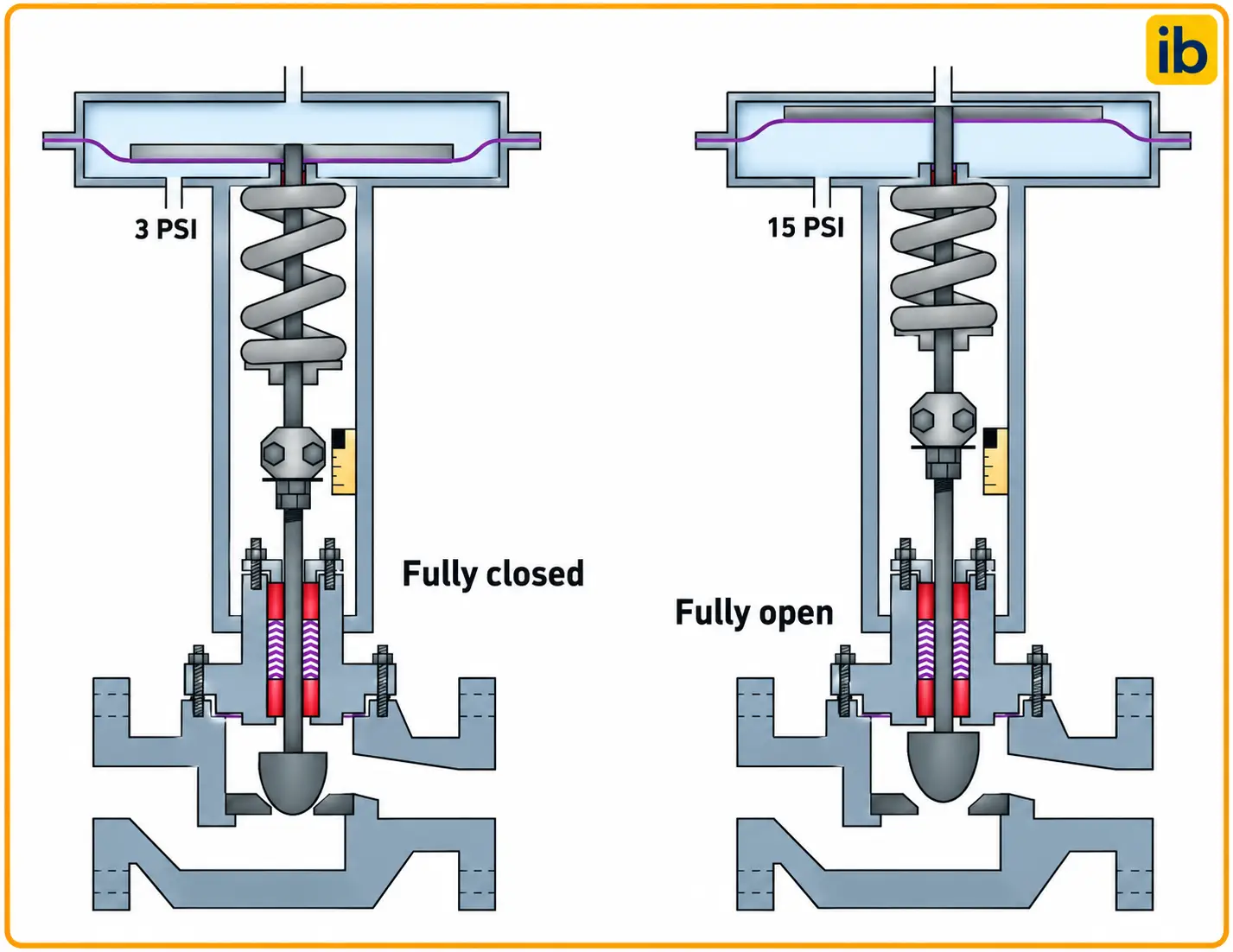
The picture shows a correctly adjusted stem connector, with the plug resting on the seat and the travel indicator reading full open just before the diaphragm reaches its limit. That coupling must be right before the spring is adjusted, and the parts involved are listed in basic parts of a control valve.
Bench Set vs Spring Range
Spring range is the pressure span that strokes the bare actuator through its rated travel against its own spring. It depends only on the spring rate, the diaphragm area and the travel, so it is a property of the actuator alone.
Bench set is the same kind of span but measured on the assembled valve, which adds packing friction and the chosen spring preload. Automation Service gives the example of an air to open valve with a 7 to 15 psi setting, where the stem starts moving at 7 psi and reaches full travel at 15 psi.
| Term | What It Means | Where It Is Found |
|---|---|---|
| Spring range | Pressure span to stroke the actuator alone | Actuator nameplate |
| Bench set | Span set on the assembled valve with no process pressure | Valve nameplate, datasheet |
| Operating range | Span actually needed in service with process forces | Commissioning records |
| Signal range | Controller or positioner output, such as 3 to 15 psi | Loop drawing |
The operating range in service is different again. Process pressure pushing on the plug adds or subtracts force, so a valve with a 6 to 15 psi setting might need 8 to 17 psi, or 4 to 13 psi, to stroke under full differential pressure.
The bench range is deliberately chosen so that it does not match the signal range. The difference between the two is what creates spare force for seat load and for overcoming process unbalance.
Why Spring Preload Decides Seat Load
Automation Service lists three forces an actuator must provide: overcoming the static unbalance from process pressure on the plug, supplying seat load for tight shutoff, and overcoming packing friction. The spring preload is how the designer shares the spring force among these jobs.
In an air to open, fail closed valve, the spring alone holds the plug on the seat when air is vented. The spring force at the closed position equals the lower spring setting pressure times the effective diaphragm area, and that force is what remains to fight process pressure, as described in fail safe valve positions.
In an air to close, fail open valve, the seat load comes from air instead. The available force is the supply pressure minus the upper spring setting pressure, multiplied by the diaphragm area, so a positioner with full supply gives much more seat load than a bare 15 psi signal.
Pressure in bar, area in cm², force in newtons (1 bar on 1 cm² = 10 N)
Example:
Area = 445 cm², lower spring setting = 0.4 bar
Spring force = 0.4 × 445 × 10 = 1780 N
Port 25 mm, port area = 4.909 cm², shutoff ΔP = 10 bar
Unbalance = 10 × 4.909 × 10 = 490.9 N, packing friction = 180 N
Seat load = 1780 minus 490.9 minus 180 = 1109.1 N
Port circumference = π × 25 = 78.54 mm, so 1109.1 ÷ 78.54 = 14.12 N per mm
Valve makers state the seat load needed for each shutoff class as a force per unit length of port circumference. Compare your result with the vendor figure for the class chosen from control valve seat leakage classes.
Seat Load Calculator for Air to Open Valves
This calculator assumes flow under the plug, where process pressure tries to lift the plug off the seat. Friction is subtracted to stay on the safe side, because it can act against the spring when the valve is closing.
When a fail closed valve passes at high differential pressure, check the lower spring setting first. A spring set a little too light is a very common cause and costs nothing to correct.
Second Example: Air to Close Seat Load
Take the same actuator fitted for air to close duty, with a bench range of 0.4 to 1.0 bar and a positioner supplied at 2.4 bar. At full output the net air force is (2.4 minus 1.0) × 445 × 10 = 6230 N.
Subtracting the same unbalance of 490.9 N and friction of 180 N leaves 5559.1 N of seat load, or about 70.78 N per mm. With only a 15 psi signal and no positioner there would be almost no spare force, which is why air to close valves normally need a positioner with full supply.
6 Essential Steps to Check the Bench Set
The Fisher 667 instruction manual asks for a certified gauge that reads the diaphragm pressure from zero up to 0.3 bar, or 5 psig, above the upper operating pressure on the nameplate. It also tells the technician to thread the spring adjuster up or down on the actuator stem until stem movement is first detected at the specified pressure.
Always approach each reading from the same direction and tap the actuator lightly, because friction causes a small difference between rising and falling pressure. Clean, dry air matters too, and moisture problems are covered in dew point in instrument air.
A properly adjusted spring shows up clearly on a valve signature test. Smart positioners plot actuator pressure against travel, and the spring line on that plot should start and finish at the nameplate pressures.
Adjusting Bench Set for Air to Open and Air to Close
Spring pushes the plug down onto the seat and air lifts it.
Spring lifts the plug and air pushes it onto the seat.
Spring and diaphragm drive a lever on a rotary shaft.
For an air to open valve, raising the lower spring setting adds seat load but also raises the pressure needed to open. Too high a value can leave the positioner unable to give full travel within its supply, a problem often reported in control valve troubleshooting.
For an air to close valve, lowering the upper spring setting increases the spare air force for shutoff. The trade off is weaker spring force to open the valve against friction when air fails, so the fail open action must still be proven.
Never adjust the spring to hide a sticking valve. If the pressure difference between rising and falling strokes is large, fix the packing or guiding first, then set the spring.
Common Bench Set Mistakes
Another mistake is testing with the positioner still connected, so the reading shows positioner behaviour instead of the spring. The working of the device itself is covered in control valve positioner working.
- Tight shutoff at the rated pressure drop.
- Full travel within the available air supply.
- Predictable fail safe action on air loss.
- Clean valve signature for diagnostics.
- Cannot fix worn seats or damaged trim.
- Cannot overcome an undersized actuator.
- Changes the opening pressure as well as seat load.
- Must be rechecked after packing or spring work.
Troubleshooting With the Bench Set
- Compare nameplate bench set with measured start and end pressures.
- Check that the stem connector gives full seating and rated travel.
- Measure rising and falling pressures to estimate friction.
- Confirm the diaphragm and casing do not leak.
- Verify supply pressure at the positioner under full demand.
- Check seat load against the shutoff class needed.
- Record results in the valve history file.
If a fail closed valve passes, the cause may be low seat load, worn trim or debris, as covered in control valve passing causes. A bench check separates the actuator side from the trim side quickly.
On emergency shutdown valves, the spring setting also affects stroke time and partial stroke results. See partial stroke testing of ESD valves for how diagnostic tests reveal spring and friction changes over time.
For wider background on actuator families, read valve actuator types and applications, and for the test gauge itself choose an accuracy class explained in pressure gauge accuracy classes.
Where Bench Set Checks Are Needed
Fisher 667 Actuator Manual
Watch a Bench Set Being Done
Bench Set FAQ
It is the range of diaphragm pressure that strokes the valve through full travel on the bench with no process pressure. It is set by adjusting the initial compression of the actuator spring.
The value is stamped on the nameplate or written in the datasheet. It decides how much force is left for seat load and for process unbalance in service.
Spring range belongs to the bare actuator and depends on spring rate, area and travel. It does not include any valve packing friction or the preload choice made on the assembled valve.
The bench set is measured on the assembled valve, so it includes packing friction and the chosen spring preload. Both are measured without process pressure in the valve body.
The actuator needs spare force to press the plug firmly on the seat and to overcome process forces. A different spring setting creates that spare force within the signal range.
For example, a 6 to 15 psi setting leaves the spring force at 6 psi for seat load in a fail closed valve. The remaining span still gives full travel at the top of the signal.
In a fail closed valve, seat load equals lower spring setting times diaphragm area, minus process unbalance and friction. A higher lower setting gives more seat load.
In a fail open valve, seat load comes from supply pressure minus upper spring setting, times the area. A positioner with full supply pressure therefore gives far more seat load than a bare signal.
You need a clean air regulator, a certified test gauge and a simple way to measure stem travel, such as a dial indicator. Fisher recommends a gauge reading at least 0.3 bar above the upper operating pressure.
Disconnect the positioner so that the reading reflects only the spring and the valve friction. Approach each reading from the same direction and stroke the valve several times.
A positioner controls travel, but it cannot create force the spring or supply cannot provide. A spring set too light still gives poor seat load in a fail closed valve at high pressure drop.
A heavy spring may stop the positioner from reaching full travel within its supply. The spring must be set correctly first, then the positioner calibrated.
Check it after any spring, diaphragm or packing work and when a valve passes or fails to reach travel. Many plants also check it on critical valves during every planned turnaround or shutdown.
Record both measured pressures each time. A slow drift in the readings between checks can reveal a tired spring, rising friction or a leaking diaphragm casing.
Related Articles
- Diaphragm Actuator vs Piston Actuator
- Control Valve Positioner Working
- Control Valve Seat Leakage Classes
- Fail Safe Valve Positions
- Control Valve Passing Causes
External References
- Fisher 667 Diaphragm Actuator Instruction Manual, Emerson
- Control Valve Actuator Bench Set Requirements, Automation Service
- Control Valve, Wikipedia
What We Learn Today
- Bench set is the diaphragm pressure span that strokes an assembled valve with no process pressure, and it differs from the actuator spring range.
- In a fail closed valve, seat load equals lower spring setting pressure times diaphragm area, minus process unbalance and packing friction.
- Check the setting with a regulator, a certified gauge and the positioner disconnected, then record both pressures and recalibrate the positioner.