Temperature Measurement in Hazardous Areas: Ex d and Ex ia Sensor Types

Share:
Temperature Measurement
Temperature Measurement in Hazardous Areas: Ex d and Ex ia Sensor Types

A standard thermocouple or RTD installed in a hazardous area without the correct protection concept is a potential ignition source for a flammable atmosphere.

The two most common protection concepts are Ex d (flameproof) and Ex ia (intrinsically safe). Each controls the ignition risk differently and imposes different constraints on the sensor, wiring, and associated transmitter.

Ex d Flameproof Ex ia Intrinsic Safety ATEX Zone Classification Temperature Class

Selecting the wrong protection concept for a hazardous area temperature sensor is a safety failure, not just a compliance issue.

Understanding Ex d and Ex ia is essential for any instrument engineer in oil, gas, and chemical industries.

Hello everyone, today we are going to learn about temperature measurement in hazardous areas using Ex d flameproof and Ex ia intrinsically safe sensor types.

We will cover what each protection concept means, how it applies to thermocouple and RTD assemblies, the zone classifications where each is used, the temperature class marking system, and a full comparison table to help you specify the right sensor for your application.
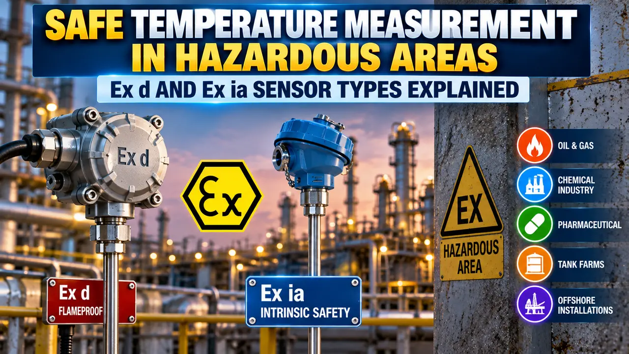
hazardous area

Why Hazardous Area Temperature Sensors Need Special Protection

A hazardous area contains, or may contain, a flammable atmosphere: a mixture of flammable gas, vapour, or dust with air in a proportion that can ignite.

Three elements are needed for ignition: a flammable substance, oxygen, and an ignition source.

Electrical equipment is a potential ignition source through two mechanisms: a spark from an electrical fault, or a hot surface exceeding the ignition temperature of the surrounding atmosphere.

Temperature sensors introduce both risks. The connection head contains terminals that can arc under fault. A sensor on a hot process can transfer heat to its external surfaces.

The IEC 60079 series defines the protection concepts, equipment groups, zones, and temperature classes governing all electrical equipment in hazardous areas.

ATEX is the European directive that mandates IEC 60079 compliance. IECEx is the international certification scheme.

Advertisement

Zone Classification and What It Means for Sensor Selection

The hazardous area zone classification determines what protection concepts are permitted for equipment in that location.

ZoneDefinitionFrequency of Hazardous AtmosphereEquipment Categories Permitted
Zone 0Flammable gas or vapour present continuously or for long periodsGreater than 1000 hours per yearCategory 1G only (e.g. Ex ia, Ex ma)
Zone 1Flammable gas or vapour likely to be present under normal operation10 to 1000 hours per yearCategory 1G or 2G (e.g. Ex ia, Ex d, Ex e)
Zone 2Flammable gas or vapour not likely in normal operation; only in abnormal conditionsLess than 10 hours per yearCategory 1G, 2G or 3G (e.g. Ex ia, Ex d, Ex e, Ex n)
Zone 20Flammable dust present continuously or for long periodsGreater than 1000 hours per yearCategory 1D only
Zone 21Flammable dust likely under normal operation10 to 1000 hours per yearCategory 1D or 2D
Zone 22Flammable dust not likely in normal operation; only in abnormal conditionsLess than 10 hours per yearCategory 1D, 2D or 3D

Zone 0 is the most demanding and permits only a small set of protection concepts. Ex d is not permitted in Zone 0 because sparks may escape during head opening.

Ex ia prevents energy from ever reaching an ignition level and is therefore Zone 0 permissible.

Ex d (Flameproof) Temperature Sensors

The Ex d protection concept works by containment. If a flammable mixture enters the connection head and ignites, the head is designed to contain the explosion without rupturing.

The enclosure achieves this through thick walls with precise flame path geometries at every joint and cable entry.

The flame path is a narrow gap long enough to cool any escaping hot gases below the ignition temperature before they reach the outside.

How Ex d Applies to Thermocouple and RTD Assemblies

The protection point
In an Ex d temperature sensor assembly, the sensor element (thermocouple or RTD) is a simple passive device that is not in itself an ignition hazard. The protection concept applies to the connection head, where the electrical terminals are located. The head must be certified as Ex d if any non-intrinsically safe circuit is connected at those terminals.
Head construction
The Ex d head is a heavy-walled enclosure (typically cast aluminium or stainless steel) with machined thread entries and flame path joints. The wall thickness and joint gap length are specified and tested per IEC 60079-1. The cover thread must engage a minimum number of turns before the joint gap is exposed this prevents rapid opening under pressure from an internal explosion.
Cable entry
The cable entry into an Ex d head must be through a certified Ex d cable gland or a certified conduit entry fitting. Standard PG-thread cable glands are not acceptable. The gland must be certified for the same gas group (IIA, IIB, or IIC) as the head. A conduit seal must be installed within 450 mm of the entry to prevent flammable gas from tracking through the conduit to other equipment.
Opening in service
An Ex d enclosure must not be opened while the circuit is energised. The marking "Do Not Open When Energised" appears on the head. A time delay (typically 10 minutes) is required after de-energising to allow any accumulated flammable gas to disperse before the head is opened. This is a significant operational constraint in maintenance-intensive plants.
Zones permitted
Ex d is permitted in Zone 1 and Zone 2 for gas hazards. It is not permitted in Zone 0. It is not a suitable protection concept for Zone 20, 21, or 22 dust hazards; a separate dust protection concept (such as Ex tD or Ex tc) is required for those locations.
Ex d flame path maintenance is critical: Any damage, corrosion, or contamination of the flame path joint surfaces in an Ex d head reduces its ability to cool escaping gases. Never apply paint, thread tape, or sealant to the flame path joint surfaces of an Ex d enclosure. Do not file or grind the joint faces to remove corrosion. If the flame path is damaged, the head must be replaced. Always clean the joint surfaces with a clean dry cloth and inspect them for pitting, scoring, or corrosion before closing the head after each maintenance visit.
Advertisement

Ex ia (Intrinsically Safe) Temperature Sensors

The Ex ia concept works by energy limitation. The electrical energy in the circuit is kept below the ignition level for the most sensitive gas group mixture.

This limit holds under normal operation and under up to two simultaneous faults.

Unlike Ex d, which contains ignition after it occurs, Ex ia prevents ignition from occurring. This makes Ex ia the safest common protection concept and the only one permitted in Zone 0.

How Ex ia Applies to Thermocouple and RTD Assemblies

Simple apparatus
A thermocouple is classified as simple apparatus under IEC 60079-11. It is a passive device that generates only a small millivolt signal and cannot store or release enough energy to cause ignition even under fault conditions. A Pt100 RTD is also simple apparatus because it is a resistive device with no stored energy. Simple apparatus does not require individual ATEX or IECEx certification, but must still meet basic requirements including the ability to withstand a 500 V AC test voltage to earth when the associated barrier is non-isolated.
Associated apparatus
While the sensor itself is simple apparatus, the transmitter or barrier connected to it in the safe area must be certified as associated apparatus. A Zener barrier or galvanic isolator limits the voltage, current, and power that can reach the hazardous area sensor terminals under any fault condition. The transmitter or DCS input card must also be certified if it is connected directly without a barrier. See the guide on Zener barriers and galvanic isolators for selection and wiring rules.
Entity parameters
The intrinsic safety system must be verified using entity parameter matching. The barrier output parameters (Uo, Io, Po, Co, Lo) must be compatible with the sensor input parameters (Ui, Ii, Pi, Ci, Li). If the barrier capacitance Co is less than the cable capacitance plus the sensor capacitance Ci, the system is safe. This verification is documented on the installation's intrinsic safety loop assessment sheet.
Cable requirements
Ex ia wiring must be run in a dedicated intrinsically safe cable or segregated from non-IS circuits. IS circuits are typically identified by blue cable or blue cable markers. They must not share a conduit, trunking, or junction box with non-IS circuits. The cable capacitance and inductance must not exceed the certified Co and Lo values of the associated barrier.
Opening in service
An Ex ia temperature sensor may be opened, inspected, and replaced in the hazardous area without de-energising the circuit, provided all work follows the IS system documentation and no non-IS tools or equipment are introduced. This is a major operational advantage over Ex d in process plants where temperature sensors require frequent maintenance or calibration.
Zones permitted
Ex ia is permitted in Zone 0, Zone 1, and Zone 2 for gas hazards (and Zone 20, 21, 22 for dust if the correct entity parameters are met). Ex ib is Zone 1 and Zone 2 only. Ex ic is Zone 2 only. The zone where the sensor is installed determines which subcategory of intrinsic safety is required.
Thermocouple extension cable in Ex ia circuits: In an Ex ia thermocouple loop, the extension cable between the thermocouple head and the safe area must be thermocouple extension cable or compensating cable of the correct type for the thermocouple (Type K extension with a Type K thermocouple, for example). Using standard copper control cable introduces a junction error at each end of the cable run equal to the cold junction compensation error at that junction temperature. Read the thermocouple grounded vs ungrounded junction guide to understand why the junction type also affects IS system verification for grounded junctions.

Temperature Class (T-Class) and Why It Matters

The temperature class specifies the maximum surface temperature of equipment under the worst normal operating conditions. The surrounding flammable atmosphere must have an auto-ignition temperature above this T-class value.

Temperature ClassMaximum Surface TemperatureExample Gases at Risk
T1450 degrees C maximumMethane (537 degrees C AIT). T1 equipment is safe for most common gases.
T2300 degrees C maximumEthyl alcohol (365 degrees C AIT). Covers most hydrocarbons safely.
T3200 degrees C maximumPetrol (246 degrees C AIT). The most common T-class in oil and gas plants.
T4135 degrees C maximumAcetaldehyde (175 degrees C AIT). Used where lower AIT gases may be present.
T5100 degrees C maximumCarbon disulfide (90 degrees C AIT T5 not sufficient for CS2).
T685 degrees C maximumDiethyl ether (160 degrees C AIT). T6 covers nearly all common flammable gases.

The T-class applies to the connection head, not to the sensor element.

A thermocouple at 800 degrees C process temperature may have a T6 Ex d head if the head is thermally isolated by sufficient sheath length.

Where the head temperature cannot be guaranteed to stay within the T-class limit, an extended neck assembly or thermal barrier between the head and the process must be specified.

Ex d vs Ex ia for Temperature Sensors: Full Comparison

Ex d Flameproof Temperature Sensor

Heavy-walled certified head. Zone 1 and Zone 2 only. Not permitted in Zone 0. No IS barrier required. Cannot be opened while energised. Certified cable glands and conduit seals required.

Ex ia Intrinsically Safe Temperature Sensor

Sensor is simple apparatus requiring no individual cert. Zone 0, 1 and 2 permitted. IS barrier mandatory in the safe area. Dedicated IS wiring required. Can be opened live in zone.

ParameterEx d FlameproofEx ia Intrinsically Safe
Protection methodContains ignition inside the enclosurePrevents ignition by limiting energy
Zone 0 permitted?NoYes (Ex ia only, not Ex ib or Ex ic)
Zone 1 permitted?YesYes
Zone 2 permitted?YesYes
Sensor certificationHead must be ATEX/IECEx certifiedSensor is simple apparatus (no individual cert needed)
Safe area barrier required?NoYes: Zener barrier or galvanic isolator
Can be opened live?No: must de-energise before openingYes: live maintenance permitted
Cable type requiredStandard multicore with certified Ex d glandsIS cable (typically blue), segregated from non-IS circuits
Conduit seal required?Yes, within 450 mm of entryNot required for IS circuits
Entity parameter check?Not requiredRequired: barrier Co/Lo must exceed cable + sensor Ci/Li
Typical applicationZone 1 and 2 process plants where live maintenance is not requiredZone 0 locations, offshore applications, and sites requiring live maintenance access

How to Read the ATEX Marking on a Temperature Sensor

Every ATEX-certified temperature sensor carries a marking that encodes the protection concept, equipment group, category, gas group, and temperature class. Reading it correctly is essential for verifying suitability for the installed zone.

Example marking
II 2 G Ex d IIB T4 Gb. Each element of this marking has a specific meaning defined by IEC 60079-0 and the ATEX directive.
II
Equipment group II: surface industry (as opposed to Group I which is mines). All oil, gas, chemical, and petrochemical equipment is Group II.
2 G
Category 2 for gas (G). Category 2G equipment is suitable for Zone 1 and Zone 2. Category 1G is required for Zone 0. Category 3G covers Zone 2 only.
Ex d
Protection concept: flameproof enclosure per IEC 60079-1. Other common codes: Ex ia (intrinsic safety), Ex e (increased safety), Ex n (non-sparking, Zone 2 only), Ex p (pressurised).
IIB
Gas group IIB: equipment is suitable for gases in group IIA and IIB (which includes ethylene, propane, methane, and most common hydrocarbons). IIC is the highest group, covering hydrogen and acetylene. A sensor marked IIB must not be used in an IIC gas environment.
T4
Temperature class T4: the maximum surface temperature of the head will not exceed 135 degrees C under any normal operating condition. Verify that the auto-ignition temperature of the hazardous gas present is above 135 degrees C before installing T4 equipment.
Gb
Equipment protection level Gb (from IEC 60079-0): suitable for Zone 1 and Zone 2. Ga is Zone 0, Zone 1, and Zone 2. Gc is Zone 2 only. This level was added to IEC 60079-0 Edition 6 (2011) and replaces the older category numbering in some standards.

Watch: Flameproof (Ex d) Solutions in Hazardous Areas Explained

Advertisement

Hazardous Area Temperature Sensor Questions Engineers Ask

What is the difference between Ex d and Ex ia protection for temperature sensors?
Ex d (flameproof) uses a heavy-walled certified head to contain internal ignition so flames cannot escape. Ex ia limits circuit energy below the ignition level even under fault. Ex d is permitted in Zone 1 and 2. Ex ia is permitted in Zone 0, 1 and 2.
Does a thermocouple need ATEX certification for use in a hazardous area?
In an Ex ia circuit, a thermocouple is classified as simple apparatus and does not require individual ATEX or IECEx certification. In an Ex d installation, the connection head must be ATEX or IECEx certified. The thermocouple element inside the head does not carry a separate certification.
Can an Ex d temperature sensor head be opened while the plant is running?
No. An Ex d enclosure must not be opened while the circuit is energised. The circuit must be de-energised and a waiting period of typically 10 minutes observed before opening. Ex ia sensors do not have this restriction and can be opened live in the hazardous area.
What does the temperature class T4 mean on a hazardous area temperature sensor?
T4 means the sensor head surface will not exceed 135 degrees C in normal operation. The auto-ignition temperature of the surrounding gas must be above 135 degrees C for T4 equipment to be safe. T6 is the most restrictive, with a maximum surface temperature of 85 degrees C.
What gas group should a temperature sensor be specified for in an oil refinery?
Most refinery applications specify gas group IIB, which covers ethylene and most common hydrocarbons. Group IIC is required in hydrogen-rich areas such as hydrotreater units. IIB equipment must not be used in IIC areas. IIA (methane group) is not suitable for most refinery service.

Related Articles on This Site

External References

Advertisement

What We Learn Today

  • Ex d temperature sensors use a certified heavy-walled head to contain internal ignition. Permitted in Zone 1 and Zone 2 only. The head must not be opened while energised. Certified Ex d cable glands and conduit seals are required at every cable entry.
  • Ex ia temperature sensors are simple apparatus requiring no individual certification. A certified IS barrier in the safe area is mandatory. Ex ia is permitted in Zone 0, 1 and 2, and the sensor can be opened live without de-energising.
  • The ATEX marking encodes the equipment group, category, protection concept, gas group, and temperature class. All must be verified against the zone classification, the process gas AIT, and the site hazardous area classification before installation.
I hope you like above blog. There is no cost associated in sharing the article in your social media. Thanks for reading!! Happy Learning!!

Leave a Reply

Your email address will not be published. Required fields are marked *