
Same sensing wire, same sheath, same everything except one weld. And that one weld changes how fast it responds and how much electrical noise it lets in.
Ok, let me explain it properly. There's no single "better" answer here. Grounded and ungrounded junctions trade speed for isolation, and picking wrong shows up as either a sluggish reading or a noisy one.
Thermocouple grounded vs ungrounded junction comes down to a single construction detail: a grounded junction welds the sensing wires directly to the protective sheath for a fast response, while an ungrounded junction insulates them from the sheath for better electrical noise immunity, and the right choice depends entirely on whether speed or isolation matters more in a given application.
Thermocouple Grounded vs Ungrounded Junction: What's Actually Different
Thermocouple grounded vs ungrounded junction is really a question about one small detail inside the probe tip.
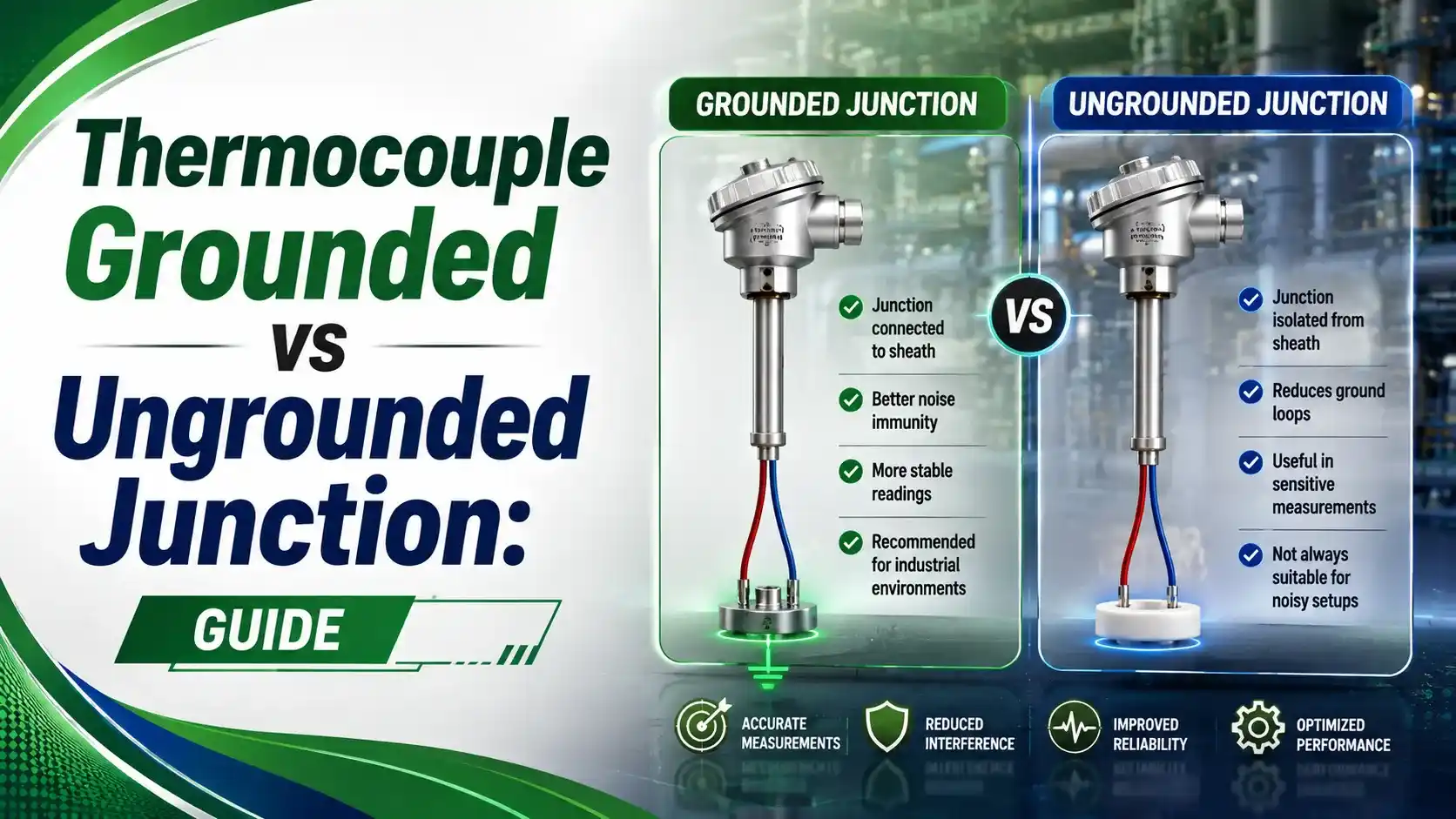
I hope it is clear, because everything else about the two designs, the sheath, the wire alloys, the extension cabling, stays the same.
The difference lives entirely at the hot junction, where the thermocouple wires either touch the metal sheath directly or sit isolated from it by a thin layer of compacted insulation.
Anatomy of the Two Junction Types
Grounded Junction
- Wires fused to the sheath at the tip
- Fast thermal response
- Electrically continuous with the sheath
Ungrounded Junction
- Wires isolated by compacted MgO insulation
- Slower thermal response
- Electrically isolated from the sheath
An exposed junction, worth mentioning for completeness, skips the sheath tip entirely and sticks the bare junction straight into the process. It's the fastest of all three, but offers no mechanical protection.
Full Comparison Table
| Characteristic | Grounded Junction | Ungrounded Junction |
|---|---|---|
| Response time | Faster, direct thermal path to sheath | Slower, insulation adds thermal lag |
| Electrical isolation | None, connected to the sheath electrically | Full isolation from the sheath |
| Ground loop risk | Higher, especially with multiple probes or noisy equipment | Essentially eliminated |
| Typical use case | Fast, clean process with a well-grounded system | Electrically noisy environments, induction heating, multiple sensors |
| Mechanical robustness | Very good, tip is a solid weld | Very good, tip is fully sealed too |
| Manufacturing cost | Slightly lower | Slightly higher |
Six Factors That Should Drive the Decision
1Speed Requirement
If the process changes quickly and fast response matters, a grounded junction has a real advantage.
2Electrical Noise Environment
Near VFDs, induction heaters, or welding equipment, an ungrounded junction avoids picking up stray electrical noise.
3Multiple Sensors, One Instrument
When several thermocouples share a common data logger, grounded junctions can create ground loops between channels.
4System Grounding Quality
A genuinely well-grounded plant reduces the practical risk of using grounded junctions, worth checking against our grounding techniques guide.
5Cathodic Protection Systems
Vessels under cathodic protection carry an intentional electrical potential, making ungrounded junctions the safer default.
6Budget and Lead Time
Grounded junctions are marginally cheaper and often more readily available off the shelf.
Try It: Response Time Comparison Calculator
Both junction types follow a first-order exponential response to a step change in temperature. Enter the values below to see how much faster a grounded junction actually responds.
Let Us Take an Example
A thermowell-mounted thermocouple sits at room temperature, 25°C, and gets suddenly dipped into a process running at a steady 200°C.
We want to know where each junction type stands just 3 seconds later.
Ti = 25°C
Tf = 200°C
t = 3 seconds
τg = 1.2 s (grounded)
τu = 3.0 s (ungrounded)
Step 1: Grounded junction
Tg(3) = 200 − (200−25) × e−3/1.2
Tg(3) = 200 − 175 × e−2.5
Tg(3) ≈ 185.6°C (91.8% of the step)
Step 2: Ungrounded junction
Tu(3) = 200 − (200−25) × e−3/3.0
Tu(3) = 200 − 175 × e−1
Tu(3) ≈ 135.6°C (63.2% of the step)
Have you got it? Good. At the exact same 3 seconds, the grounded junction has already closed most of the gap, while the ungrounded junction is still noticeably behind the true process temperature.
Ok, let me explain why this matters practically. On a fast batch process where a few seconds of lag changes a control decision, that gap is the whole reason to choose grounded.
On a noisy electrical environment, that same gap is the price worth paying for a clean signal.
Why Ground Loops Happen With Grounded Junctions
A grounded junction is electrically continuous with the sheath, and the sheath usually touches the process vessel, which is itself grounded somewhere.
If the instrument's signal reference is grounded at a different point with a different potential, a small current flows through the measurement circuit itself. That's a ground loop.
According to Ashcroft's guide to grounded vs ungrounded thermocouple junctions, this is exactly why ungrounded junctions are the standard recommendation whenever electrical isolation is a real concern.
An ungrounded junction breaks this path entirely, since the sensing wires never touch the sheath, and the sheath's ground potential simply has nowhere to interfere.
A Step-by-Step Selection Approach
Assess the electrical environment
Check for nearby VFDs, induction heaters, welding equipment, or cathodic protection systems.
Weigh response time needs
Determine how quickly the process actually changes and whether that speed genuinely matters for control.
Check for multiple sensors on one instrument
Multiple grounded junctions feeding a shared data logger raise ground loop risk noticeably.
Verify plant grounding quality
A genuinely solid, well-maintained grounding system reduces, but doesn't eliminate, the practical risk with grounded junctions.
Default to ungrounded when unsure
If noise risk is uncertain, an ungrounded junction is the safer general-purpose choice, at a small cost in response speed.
Document the choice and reasoning
Record which junction type is installed and why, so future troubleshooting doesn't have to re-derive the decision.
Good Practices for Grounded and Ungrounded Junctions
✓ Do
- Choose ungrounded junctions near VFDs, induction heaters, or other electrically noisy equipment
- Choose grounded junctions when fast response genuinely drives the control decision
- Use ungrounded junctions by default on vessels with cathodic protection
- Check grounding quality across the plant before assuming grounded junctions are safe
✗ Don't
- Assume grounded junctions are always fine just because the plant seems well grounded
- Mix grounded and ungrounded junctions on the same multi-channel instrument without checking
- Choose ungrounded junctions where the extra thermal lag would actually hurt process control
- Ignore a history of erratic, noisy readings as a possible ground loop symptom
Worth Reading if You Want to Go Deeper
Questions Students and Technicians Often Ask
External References
- Grounded vs. Ungrounded Thermocouple Junctions, Ashcroft
- Grounded vs Ungrounded Thermocouple Junction: What Engineers Often Get Wrong, Tempsens
What we learn today
- A grounded junction welds the sensing wires to the sheath for fast response, while an ungrounded junction isolates them for better electrical noise immunity.
- An exposed junction, the fastest of all three, skips sheath protection entirely and is used only where mechanical protection isn't needed.
- A worked example showed a grounded junction reaching 91.8% of a step change in 3 seconds, versus 63.2% for an ungrounded junction with a longer time constant.
- Ground loops happen because a grounded junction is electrically continuous with the sheath, which usually touches a separately grounded vessel or structure.
- The right choice depends on weighing response speed against electrical noise risk, not on one type being universally better.