
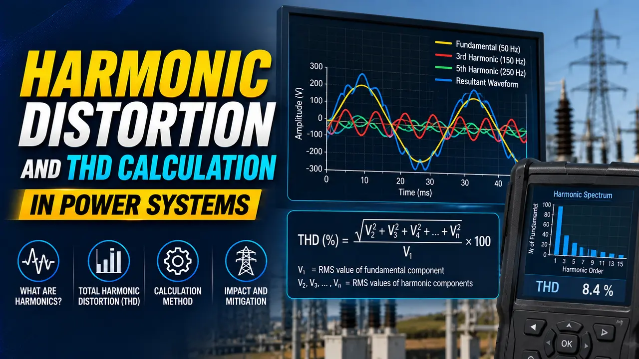
Harmonic distortion is the presence of voltages or currents at integer multiples of the supply frequency.
In a 50 Hz system, the 3rd harmonic is 150 Hz, the 5th is 250 Hz, the 7th is 350 Hz.
Total Harmonic Distortion (THD) is the single number that summarises how much harmonic content a waveform contains relative to its fundamental.
This guide explains how harmonics are generated, how to calculate THD step by step, what IEEE 519 limits require, and includes a live THD calculator.
Every non-linear load on an AC power system draws current in pulses rather than a smooth sine wave. That pulsed current contains harmonics.
When enough non-linear loads share the same bus, the harmonic currents add up, distort the bus voltage, and cause problems for every other device on the same supply.
Why Harmonic Distortion Matters in Industrial Plants
A perfectly sinusoidal 50 Hz current contains only the fundamental frequency. No harmonics, no distortion. Real industrial loads are never perfectly linear.
Variable frequency drives, uninterruptible power supplies, switch-mode power supplies, arc furnaces, and rectifiers all draw current in a non-sinusoidal pattern. Each of these devices injects harmonic currents back into the supply network.
These harmonic currents travel through the supply impedance and create harmonic voltages. Those voltages then appear at every other load connected to the same bus.
The 3rd harmonic (150 Hz) is dominant in systems with single-phase switch-mode power supplies such as computers and office equipment. Unlike the 5th harmonic, 3rd harmonics do not cancel in a balanced three-phase system. They add up in the neutral conductor, which is why neutral overcurrent is a common problem in commercial buildings with heavy IT loads.
Harmonic distortion causes measurable real-world problems. Motors run hotter because harmonic currents create additional iron losses and copper losses.
Capacitor banks can resonate with the system inductance at harmonic frequencies and be destroyed. Protection relays may misoperate. Transformers derate and overheat.
This is why IEEE 519 sets limits on harmonic distortion at the point of common coupling between the utility and the customer.
THD Formula and How to Calculate Harmonic Distortion
The THD formula expresses total harmonic distortion as a percentage of the fundamental component.
Where:
I1 = RMS value of the fundamental component (50 Hz or 60 Hz)
I2 = RMS value of the 2nd harmonic (100 Hz or 120 Hz)
I3 = RMS value of the 3rd harmonic (150 Hz or 180 Hz)
In = RMS value of the nth harmonic
The same formula applies to voltage THD, replacing I with V.
Total RMS current:
IRMS = sqrt(I1² + I2² + I3² + ... + In²)
So: THD = sqrt(IRMS² minus I1²) / I1 × 100%
In most power systems, only odd harmonics are significant. Even harmonics (2nd, 4th, 6th) tend to cancel due to the symmetry of the AC waveform.
The most important harmonics to measure in an industrial plant are the 5th, 7th, 11th, and 13th.
IEEE 519 sets harmonic limits at the PCC — the point where the utility and the customer share a common connection. Measuring inside the customer's facility will almost always give higher THD values, because harmonic currents have not yet been attenuated by the supply transformer impedance.
If your power quality analyser reads high THD at a motor control centre, compare that reading against the THD at the main incomer before concluding the system is non-compliant with IEEE 519. The standard applies at the PCC, not at every panel within the facility.
Worked Example: THD Calculation for a VFD Installation
A 415 V industrial bus feeds a variable frequency drive. The power quality analyser measures the following current harmonics.
I3 (3rd harmonic, 150 Hz) = 2 A
I5 (5th harmonic, 250 Hz) = 28 A
I7 (7th harmonic, 350 Hz) = 12 A
I11 (11th harmonic, 550 Hz) = 4 A
I13 (13th harmonic, 650 Hz) = 2 A
All other harmonics less than 1 A (negligible)
I3² = 2² = 4
I5² = 28² = 784
I7² = 12² = 144
I11² = 4² = 16
I13² = 2² = 4
Step 2: Sum the squares
4 + 784 + 144 + 16 + 4 = 952
Step 3: Take the square root
sqrt(952) = 30.85 A
Step 4: Divide by the fundamental and multiply by 100
THD = 30.85 / 100 × 100 = 30.85%
This exceeds the IEEE 519 current THD limit of 20% at most industrial buses.
A passive harmonic filter or an 18-pulse rectifier would bring this into compliance.
4 Common Sources of Harmonic Distortion in Plants
IEEE 519 Harmonic Distortion Limits
| Voltage at PCC | Individual Voltage Harmonic Limit | Total Voltage THD Limit | Current THD Limit (Isc/IL 20 to 50) |
|---|---|---|---|
| 69 kV and below | 3.0% | 5.0% | 8.0% |
| 69 kV to 161 kV | 1.5% | 2.5% | 5.0% |
| 161 kV and above | 1.0% | 1.5% | 2.0% |
The IEEE 519 current THD limit depends on the ratio of short-circuit current (Isc) to the maximum demand load current (IL) at the PCC.
A higher Isc/IL ratio means the system is stiff, so higher harmonic currents are permitted. The table above shows limits for a typical industrial bus with Isc/IL of 20 to 50.
Many older assessments were incorrectly applying the limits at internal switchboards, which led to unnecessary and expensive harmonic filtering. The 2022 edition also added guidance on how to handle systems with multiple harmonic sources at different buses within a large facility, using an aggregation method rather than simple addition of all harmonic currents.
If your plant has a harmonic compliance report that was written before 2014, it may be worth having it reviewed against the current IEEE 519-2022 requirements.
THD Calculator for Power Systems
Watch: How to Calculate THD and TDD Explained (Eaton)
Questions Engineers Ask About Harmonic Distortion
Related Articles on This Site
- Power Quality Issues in VFD and PLC Systems
- Power Factor Correction Explained
- RMS Value Explained: Why AC Measurements Use RMS
- Active, Reactive and Apparent Power Explained
- How to Calculate Capacitor Bank kVAR Requirement
External References
- IEEE 519-2022: Recommended Practice for Harmonic Control in Electric Power Systems | IEEE
- Harmonic Mitigation and Power Quality Solutions | Eaton (2024)
What We Learn Today
- Harmonic distortion is caused by non-linear loads such as VFDs and switch-mode power supplies injecting currents at integer multiples of the supply frequency into the network.
- THD = sqrt(sum of harmonic squares) / fundamental × 100%. The 5th and 7th harmonics dominate in most industrial plants with 6-pulse rectifiers.
- IEEE 519-2022 sets THD limits at the point of common coupling. For a typical industrial bus at 69 kV and below, the limit is 5% voltage THD and 8% current THD.